English
19
HIMOD−C
5.2 − Fan connections
The fan is electrically feeded by an autotransformer
that is connected by the constructor in order to obtain
the nominal air flow and the Available External Static
Pressure (AESP).
To change the factory connection proceed as follow:
− identify the unit’s graph;
− choose the curve’s point where both the air flow
and the static pressure are the most suitable for the
installation;
− check the factory fan blocks connection ( or )
and correct if necessary (see Fig. 12);
− find the output connectors and the bridges corre-
sponding to the graph values (see para. 5.3;
− connect the bridges and the output connectors;
− connect the 400V supply cables to the C" termi-
nals.
After a wiring modification, execute a
loadless test on the autotransformer.
Check the voltage of each wire, in order
not to damage the transformer (always
refer to the output voltage column va-
lues).
N.B. A FAN SPEED VARIATION CHANGES THE WOR-
KING CONDITION OF THE UNIT.
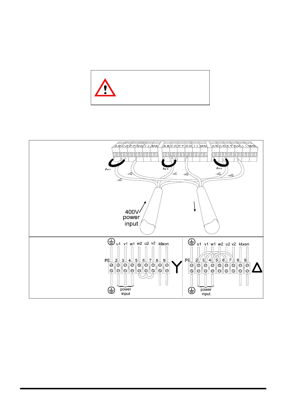
Fig. 12 − Example of electrical connection to the autotransformer
AUTOTRANSFORMER
In the example picture, the power supply
voltage required is 260 V, at 50 Hz.. The fan
blocks are connected.
260V
autotransformer
output
E
E
E
FAN MOTOR
Reference colors:
u1 : brown v1 : light blue
w1 : black u2 : red
v2 : grey w2 : orange
klixon: white PE : yellow/green
 Loading...


