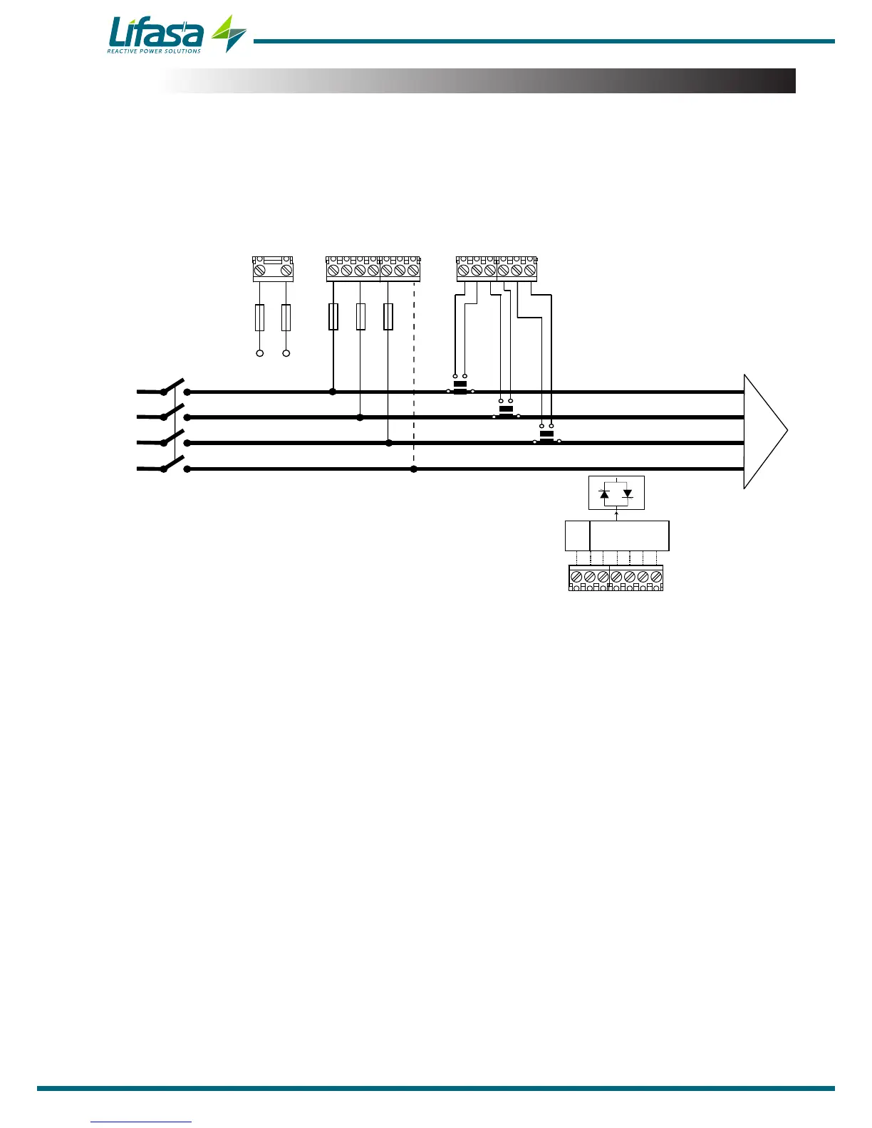
3.5.- CONNECTION DIAGRAM
3�5�1�- 3 VOLTAGES + NEUTRAL AND 3 CURRENTS, CONTROLLER MASTER CONTROL
VAR FAST 6 MODEL�
Connection type: 3U.3C
VLN
IL2
S1
L1
L2
L3
N
VL1 VL2 VL3
S1 S2
P1
P2
S1 S2
P1
P2
S1 S2
P1
P2
S1 S1S2 S2 S2
IL3
IL1
A1 A2
Power Supply
COM 1 2 3 4 5 6
COM
ACT C1...C6
Power Supply
Figure 3: 3 voltages + Neutral and 3 currents, Controller MASTER control VAR FAST 6 model�
Note: If the connection layout mentioned above is not respected, you must adjust the phase
following the procedure described in section "5�6�- PHASE CONNECTION”
Note: In this type of connection, the connection from Neutral to V
LN
is not mandatory.
14