C4,C4P / C8, C8P Installation Manual
2 3
1
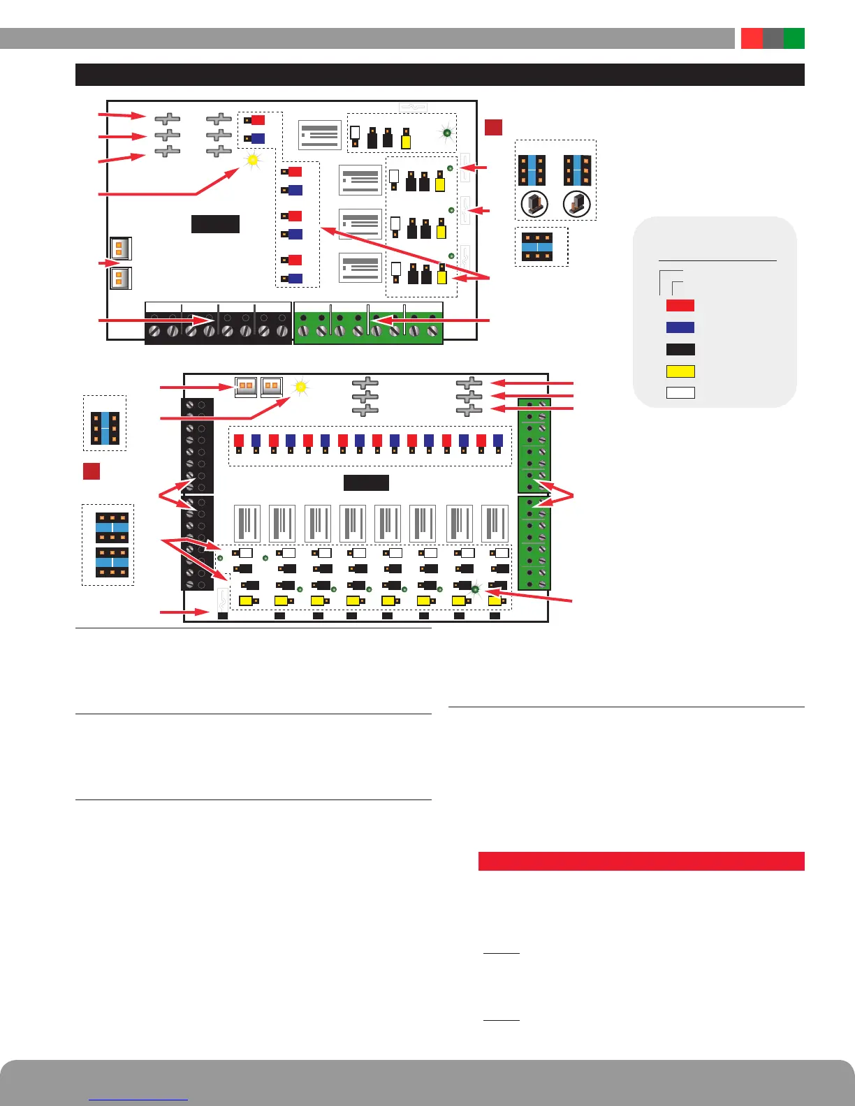
FlexIO Connectors
These connectors pass the FAI and Fault signals to and
from the C4/C4P/C8/C8P board and pass the FlexIO buss on
to other accessory boards in the system.
2
Fault LED (FLT) – Yellow
This LED lights when the C4/C4P/C8/C8P detects a ruptured
output fuse. This fault condition also transmits to the FPO
power supply.
3
Zone Inputs (IN1 – IN4/IN8)
These are the zone input terminal strips. These terminal strips
are removable and accept wire sizes from AWG14 – AWG22.
The terminals are labeled on the PC board near the terminal
strip. See the Input Wiring section of this manual for more
information.
• When using a relay contact input, the contact is connected
across the A and B terminals. When configured for a relay
contact input, it is normal to measure a voltage across these
two terminals. This voltage is current limited and will not
damage the activation contact.
• When using a voltage input, the voltage is connected to
the B terminal. The activation voltage must be common
grounded with the system voltage. The activation voltage
must be between 12 and 24VDC nominal.
• When using an open collector (transistor) input, place a jumper
across the A and B terminals and connect the open collector
to the B terminal. Note that the input source must be common
grounded with the C4/C4P or C8/C8P board’s power source.
4
Configuration Jumpers (xA–xF)
These jumpers program the zone’s input, output, and FAI
operation. Jumpers are color coded for ease of program-
ming and jumper numbers correspond with the zone
number (e.g. 1A is jumper A for Zone 1).
OBSERVE JUMPER ORIENTATION CAREFULLY - See the
Common Jumper Settings Chart for more information.
Jumpers and their possible settings are as follows:
• Jumper A - RED (Zone FAI Enable)
This jumper enables or disables FAI for the selected zone.
The FAI control input is on the FPO power supply board.
See Appendix A of the FPO manual for more information
on the FAI Input.
Pos. 1 (FAI Enabled) When this jumper is placed in posi-
tion 1, the zone's output will invert when the input
is active. This is typically used to drop power to
maglocks on a fire alarm condition.
Pos. 2 (FAI Disabled) When this jumper is in position 2,
FAI will have no effect on the zone's output.
Power Control Accessory Overview
RL8 RL7 RL6 RL5 RL4 RL3 RL2 RL1
B1
B2
BR
B1
B2
BR
FlexIOFlexIO
INPUT FIELD WIRING
C8/C8P
F7 F6 F5 F4 F3 F2 F1
I
Note Jumper
Position
Orientation
F
E
C
D
1 2
1 2
A B
2
1
FAULTFAULT
OUTPUT FIELD
WIRING 1–4
OUTPUT FIELD
WIRING 5-8
2
1
8A 8B
2
1
7A 7B
2
1
6A 6B
2
1
5A 5B
2
1
4A 4B
2
1
3A 3B
2
1
2A 2B
2
1
1A 1B
8E 7E 6E 5E 4E 3E 2E 1E
7D8D 6D 5D 4D 3D 2D 1D
8F 7F 6F 5F 3F 2F 1F
7C8C 6C 5C 4C 3C 2C 1C
21 21 21
21 21 21 21 21 2121
21 21 21 21 21
B2
BR
B1
INPUT FIELD WIRING 1–4 OUTPUT FIELD WIRING 1–4
FlexIOFlexIO
O1A+
O1B-
O2A+
O2B-
O3A+ O3B- O4A+ O4B-IN1A IN1B IN2A IN3A IN3B IN4A IN4BIN2B
FAULTFAULT
1
2
1
1
2
2
1
2
1
2
1
2
1
2A
2B
3A
3B
4A
4B
1B
1A
2F 2E
1F 1E
1D1C
C4/C4P
2 1
I
Important: Note Jumper
Position Orientation
C D
A
B
2
1
F E
F8
W
1
2
2
1
R
R
R
R
Y
W
W
B
k
Bk
Bk
BL
BL R BL R BL R BL R BL R BL R BL R BL
BL
BL
BL
Y Y Y Y Y Y Y Y
W W W W W W W W
B
k Bk
Bk Bk Bk Bk Bk Bk Bk Bk
Bk Bk Bk Bk Bk Bk
2D2C
1
2
Y
B
k
1
2
1
W
B
k
1
2
Y
Bk
3F 3E 3D3C
1
2
1
W
B
k
1
2
Y
B
k
4F 4E 4D4C
A FAI
INVERT input
INVERT output
WET/DRY output
V SELECT
B
F
C&E
D
Reference
Jumper Color
JUMPER
PROGRAMMING
RED
BLUE
BLACK
YELLOW
WHITE
I
Note: The relay contact output
has a suppression diode across
it, and cannot be used to switch
AC voltage.
To switch DC voltage with these
contacts, Terminal “B” should
be positive, “A” negative.”

 Loading...