C4,C4P / C8, C8P Installation Manual
6 7
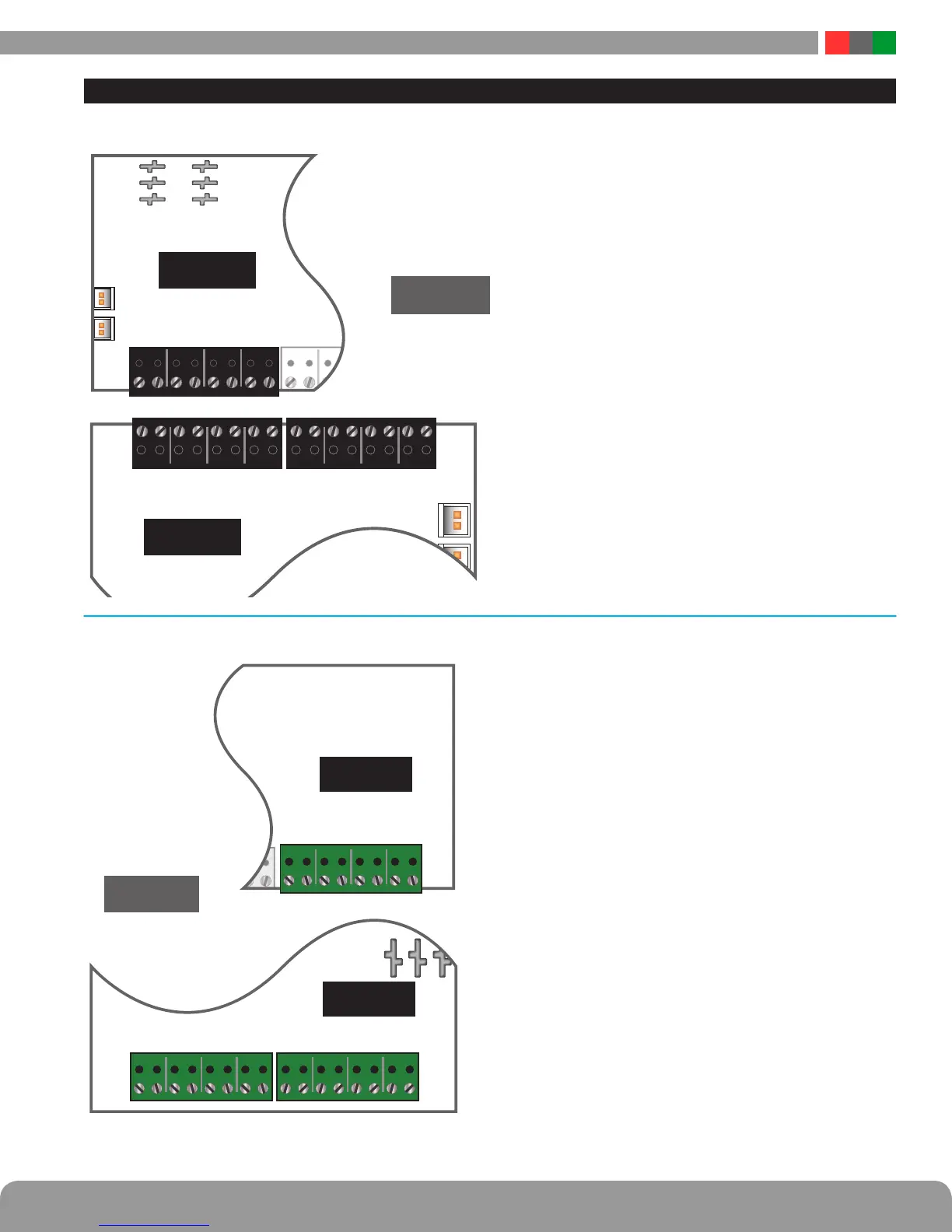
Input and Output Wiring
INPUT WIRING
IN 4B
IN 4A
IN 3B
IN 3A
IN 2B
IN 2A
IN 1B
IN 1A
IN 8B
IN 8A
IN 7B
IN 7A
IN 6B
IN 6A
IN 5B
IN 5A
C8/C8P
C4/C4P
IN 1A
IN 1B
IN 2A
IN 2B
IN 3A
IN 3B
IN 4A
IN 4B
INPUTS
Each input on the C4/C4P and C8/C8P has an “A” terminal and
a “B” terminal.
• When using a relay contact to activate the input, the
contact is placed across these terminals. It is normal to
measure a voltage across these terminals when set for
a relay contact input.
• When set for a voltage input, the voltage to activate the
zone is placed on the “B” terminal. The “A” terminal is
left disconnected. Note that the voltage used to acti-
vate the zone must be common grounded with the C8
board’s power source.
• To use a DC ground or an open collector (transistor) as
an input, place a wire jumper across the “A” and “B”
terminals and connect the ground/open collector to the
“B” terminal to activate the input. Note that the input
source must be common grounded with the C4/C4P or
C8/C8P board’s power source.
OUTPUT WIRING
C8/C8P
OUTPUTS
4B -
4A +
3B -
3A +
2B -
2A +
1B -
1A +
4B -
4A +
3B -
3A +
2B -
2A +
1B -
1A +
8B -
8A +
7B -
7A +
6B -
6A +
5B -
5A +
NOTE - Output polarity has changed -
Verify polarity via markings on the PCB
Each output on the C4/C4P and C8/C8P has an “A” termi-
nal and a “B” terminal. The usage of these terminals varies
based on the setting of jumpers C and E for the zone.
• When set for a relay contact output, these terminals are
the output of the relay. No voltage is output from these
terminals when set for a relay contact output.
Note: The relay contact output has a suppression diode
across it, and cannot be used to switch AC voltage. To
switch DC voltage with these contacts, the polarity of the
voltage being switched should match the terminal mark-
ings.
• When set for a wet/voltage output, these terminals pro-
vide the output voltage. Observe the polarity markings
on the PCB for each output.
I
CAUTION When powering magnetic loads such as
maglocks, door strikes, solenoids, etc, each of these
loads must have a reverse protection diode either built-in
or external to the device.

 Loading...