C4,C4P / C8, C8P Installation Manual
8 9
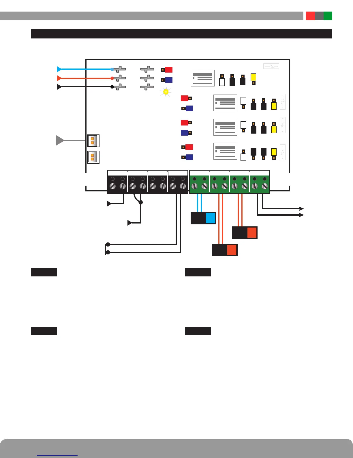
C4/C4P Application Example
Zone 1
24V Mag Lock Output, Voltage Input, with FAI
This zone shows a typical 24V Mag Lock application, using
a voltage input on the zone. The door will unlock upon an
FAI signal being received from the FPO Power Supply.
Jumper Positions: A-1
|
B-1
|
C-2
|
D-1
|
E-2
|
F-2
Zone 2
12V Door Strike Output, Open Collector (transistor) Input,
no FAI
This zone shows a typical 12V Door Strike application, us-
ing an open collector (transistor) input on the zone. The
door will remain locked during a fire alarm condition.
Jumper Positions: A-2
|
B-1
|
C-2
|
D-2
|
E-2
|
F-1
Zone 3
12V Reader Power, no control input, no FAI
This zone shows continuous 12V auxiliary power for pow-
ering a device such as a reader. Power will remain during a
fire alarm condition.
Jumper Positions: A-2
|
B-2
|
C-2
|
D-2
|
E-2
|
F-2
Zone 4
NC Relay Contact Output, NC Relay Contact Input, with FAI
This zone shows a NC relay contact output slaving off of
a NC relay contact input. This application can be used to
protect the low-current integral relays in an access control
panel and instead use the higher current relays on the C4 to
control the locks.
Jumper Positions: A-1
|
B-1
|
C-1
|
D-1
|
E-1
|
F-2
NC Dry
Contact
Out
NO Connection
Open Collector (Transistor) In
DOOR
STRIKE
12V
+
–
READER
12V
+
–
MAG
LOCK
24V
+
–
+12/24V Voltage IN
NC Contact
FlexIO
B2
BR
B1
FlexIOFlexIO
O1A O1B O2A O2B
O3A O3B O4A O4BIN1A IN1B IN2A IN3A IN3B IN4A IN4BIN2B
FAULTFAULT
2
1
2
1
2
1
1
2
2
1
2
1
2
1
2
1
2A
2B
3A
3B
4A
4B
1B
1A
2F 2E 2C 2D
3F 3E 3C 3D
4F 4D
1F 1E 1D1C
4E 4C
B1 24V
B2 12V
BR
INPUTS OUTPUTS
R
Y
Y
Y
W
W
W
W
R
R
R
B
L
BL
BL
BK
BK
BK
BK
BK
BK
BK
BL
– +– +– +– +
Y
B
K
Note: For UL Compliance, any locking device shall be configured for fail safe operation upon
occurrence of an alarm as shown with a normally closed relay contact

 Loading...