M8 / M8P Installation Manual
6 7
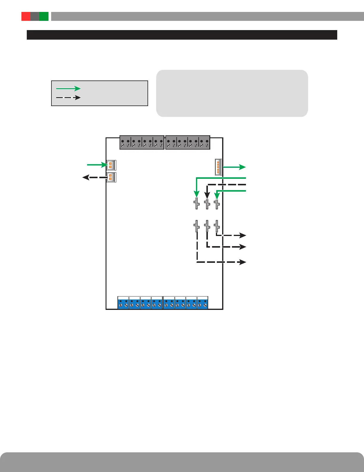
Connecting the Power Control Module
h
Remove all AC and battery power from the FPO system before adding or replacing a power control board.
FlexIO continues to
other accessories
FlexIO in from System
Required Connections
Optional Connections
Each of the B1, B2, BR, and FlexIO busses has two connectors.
These connectors may be used interchangeably.
For example: FlexIO from the power supply may be connected
to either of the M8's FlexIO connectors, the Main DC voltage
source may connect to either B1 terminal, etc.
BR in from System
Input from Main DC voltage source
Input from Second DC source (optional)
BR B2 B1
A A A AB B B B A B A B A B A B
Main DC voltage continues
to other accessories
Second DC Source continues
other accessories
BR continues to
other accessories
SPI connection to NL4
OUTPUT FIELD WIRING 1-8
O5A
O5B
O6A
O6B
O7A O8B
– +– +
O1A
O1B
O2A
O2B
O3A O3B O4A O4B
– +– +– +– +
O8A
– + – +
O7B
INPUT FIELD WIRING 1–8
 Loading...
