M8 / M8P Installation Manual
8 9
Input and Output Wiring
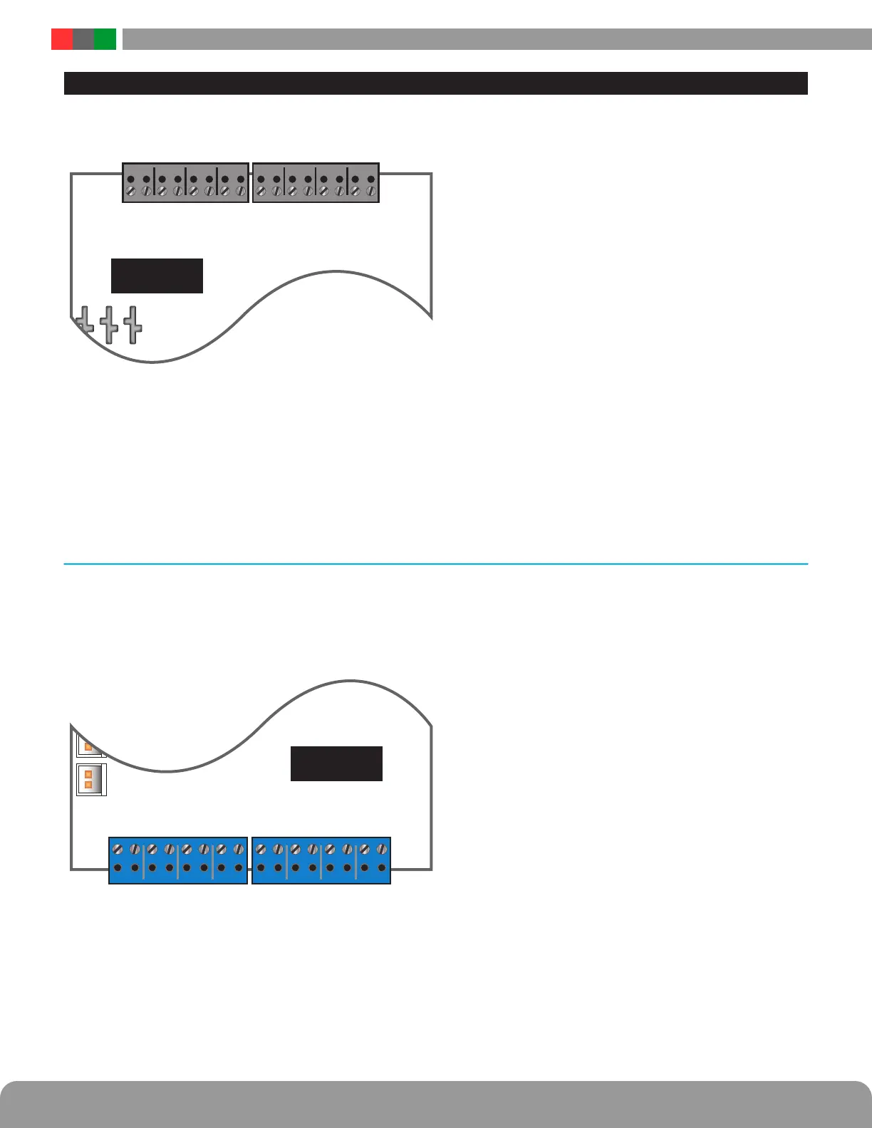
INPUT WIRING
M8/M8P
IN1 IN2 IN3 IN4 IN5 IN6 IN7 IN8
A A A AB B B B A B A B A B A B
INPUT FIELD WIRING 1-8
Each input on the M8/M8P has an “A” terminal and a “B” ter-
minal.
• When using a dry contact to activate the input, the con-
tact is placed across these terminals. It is normal to
measure a voltage across these terminals when set
for a dry contact input.
• When set for a voltage input, the voltage to activate the
zone is placed on the “B” terminal. The “A” terminal is
left disconnected. Note that the voltage used to acti-
vate the zone must be common grounded with the M8
board’s power source.
• To use a DC ground or an open collector (transistor) as
an input, place a wire jumper across the “A” and “B”
terminals and connect the ground/open collector to the
“B” terminal to activate the input. Note that the input
source must be common grounded with the M8 board’s
power source.
OUTPUT WIRING
M8/M8P
OUT1 OUT2 OUT3 OUT4 OUT5 OUT6 OUT7 OUT8
OUTPUT FIELD
WIRING 1–4
OUTPUT FIELD
WIRING 5-8
Each output on the M8/M8P has a “+” and “-” marked adja-
cent to the terminal to indicate polatity.
I
CAUTION When powering magnetic loads such as
maglocks, door strikes, solenoids, etc, each of these
loads must have a reverse protection diode either built-in
or external to the device.
 Loading...
