Do you have a question about the Lifetime 60066 and is the answer not in the manual?
Benefits and process for registering your product online.
Contact information for customer support and assistance.
Critical warnings about assembly and product use to prevent injury or damage.
Important initial steps and considerations before starting assembly.
Lists necessary tools and parts for the assembly process.
Comprehensive list of all parts and hardware included in the kit.
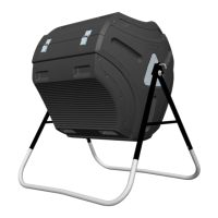
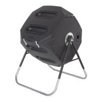
Visual guide to identifying main composter and kit parts.
Visual guide to identifying all hardware components.
Lists hardware, small parts, main parts, and tools needed for base frame assembly.
Instructions for initial assembly of the base frame.
Attaching the legs to the A-frames using screws.
Guide for assembling the locking pin mechanism.
Positioning the base and inserting the locking pin.
Attaching inner housing brackets to the A-frames.
Lists hardware and small parts needed for tumbler assembly.
Attaching mounting end plates to end panels.
Assembling components for tumbler rotation mechanism.
Applying grease to the sleeve for smooth operation.
Attaching the end panel with mounting plate to the base.
Fastening the end panel to the base frame.
Orienting and securing the second end panel.
Attaching the main panel/lid to the end panels.
Installing the ventilation tube into the end panels.
Securing panels using double hook straps.
Fastening double hook straps with screws.
Securing the second panel/lid with screws and nuts.
Installing latch assemblies onto the panel.
Installing pinned hinges on the tumbler.
Attaching hinge tubes to the lid.
Installing latch hooks on the opposite end of the lid.
Inserting blow hole plugs into the front panel.
Aligning and connecting the lid to the tumbler.
Procedure to position the latch assembly wire behind the latch hook.
Action to press the latch downwards to secure the lid.
Details of the 5-year limited factory warranty, including exclusions and claims.
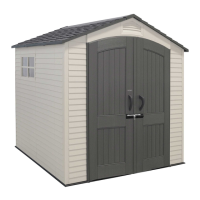
| Product Name | Lifetime 60066 Outdoor Storage Shed |
|---|---|
| Material | High-Density Polyethylene (HDPE) |
| Door Type | Double Doors |
| Assembly Required | Yes |
| Warranty | 10-Year Limited Warranty |
| Ventilation | Two screened vents |
| Lockable | Yes |