-10-
LIFEWARMER
™
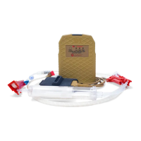
THERMAL INFUSION SET (TIS) –
For Infusion of IV Solutions
•
Standard spike with vent
•
15 micron particle lter
•
Luer activated injection sites
•
Male Luer lock adapter
•
Tubing length: 80” (230cm) long
•
Priming volume: 16 mL
TIS USE: (Use Aseptic Technique):
1. Open pouch where indicated. Remove tubing set
and close roller clamp. DO NOT place tubing, or
protective end caps in sterile eld.
2. Remove Spike protector end cap. Insert spike into
the uid container. Note: keep vent cap closed
unless infusing from a rigid solution container.
3. Fill the drip chamber by squeezing the drip
chamber until approximately half full.
4. Remove protector end cap from male Luer adapter.
5. Slowly open roller clamp to prime tubing and purge
air. Invert and tap injection ports while priming. Once
primed, close roller clamp.
6. Attach adapter to vascular access device. Twist to secure
Luer lock connection.
7. Slowly open roller clamp and adjust for desired ow rate.
Luer Activated Injection Site:
Use only standard Luer connection devices. DO NOT USE needles or blunt cannulas to access the swabable valves.
U
sing a sterile alcohol pad, swab the Luer activated surface and let it air dry. Carefully connect the syringe or Luer
connector STRAIGHT into the valve in a clockwise twisting motion. To disconnect, twist counter clockwise. Flush the
Luer activated site after each use per facility protocol.
To Initiate Fluid Warming:
1. Completely prime the system following the steps above, purging all air
from the line, and start infusion at desired ow rate. (Note: 7 mL/minute
minimum ow rate is needed to initiate warming. Once warming begins
(Flashing Blue LED), User may titrate to lower ow rates if desired.
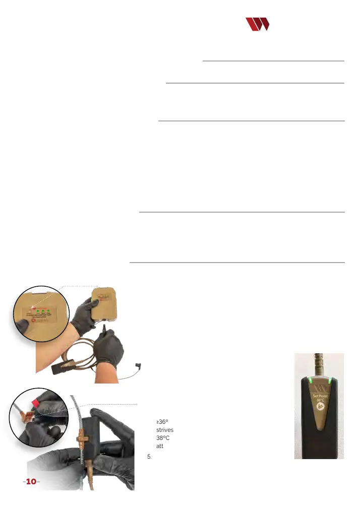
2. Briey press the ‘Status’ button on the Battery to check battery
charge. Three green LEDs indicate a full charge. One LED or
no LEDs indicate insucient charge to operate the device. If
the Battery has sucient charge, remove the protective cover
and connect the Controller to the Battery. A green blinking
Controller LED indicates system is ready for use. (Image 1)
3. Connect the Controller to the circuit cartridge
of the TIS by removing its red protective cap
exposing the circuit cartridge. (Image 2)
4. Connect the Controller to the tubing by rmly
pressing the tubing’s circuit cartridge into the
connector slot on the Controller (Image 3). A
Blue ashing LED indicates the uid is warming
but is <36ºC. A solid green LED indicates uid is
≥36ºC and < 44ºC. At steady state, the System
strives to maintain infusion at a set point of
38ºC +/- 2ºC. (Image 4) Note: the System will
attain set point only during owing infusion.
5. Depending on uid temperature and ow rate, the
User may need to adjust the infusion rate to stay in the set point range.
6. When infusion is complete, disconnect the Controller
from the TIS and battery to conserve power.
QUANTUM OPERATION:
To begin using the Quantum Blood & Fluid Warming System, select the
appropriate tubing set for infusion of IV solutions (TIS) or transfusion of blood/blood products or IV solutions (TTS-B).
F
ollow the directions on page 9 for either the TIS or TTS-B tubing selected.
WARNING:
TIS IS NOT for standalone use with blood products.
Only uid path and area under protective end caps are STERILE.
Status Button
Image 1
Circuit cartridge
Image 2
Image 3
Image 4