Lighthouse ApexRemote Operating Manual
4-4 248083447-1 Rev 1
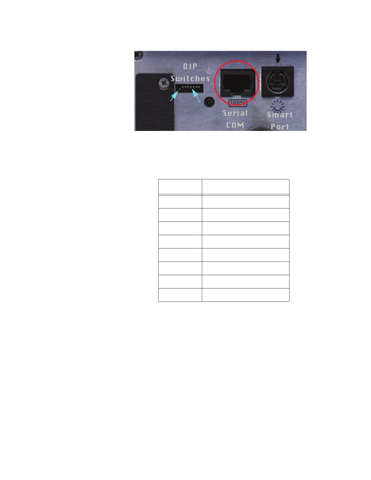
Figure 4-2 Serial COM Port
The connector pinouts are shown in Table 4-4.
To connect the instrument to an RS-485 network:
1. Make sure the SmartPort cable is disconnected from the
instrument.
2. Install the ApexRemote in a perpendicular position with its Inlet
barb upward. Connect one end of a CAT5e cable to the Serial COM
port on the instrument (shown in Figure 4-2).
3. Connect the other end of the cable to an available RS485 port on an
LWS 485 Gateway, an LWS System Control Cabinet RS485 port or
other similar equipment port.
Table 4-4 RJ45 Pinouts
RJ45 Pin Signal Name
1 RS-232-TX (Output)
2 RS-232 RX (Input)
3 RESERVED for future use
4 RS-485B
5 RS-485A
6 RESERVED for future use
7 24VDC
8 GROUND
Switch 1 through 5
 Loading...