Install
248083447-1 Rev 1 7-5
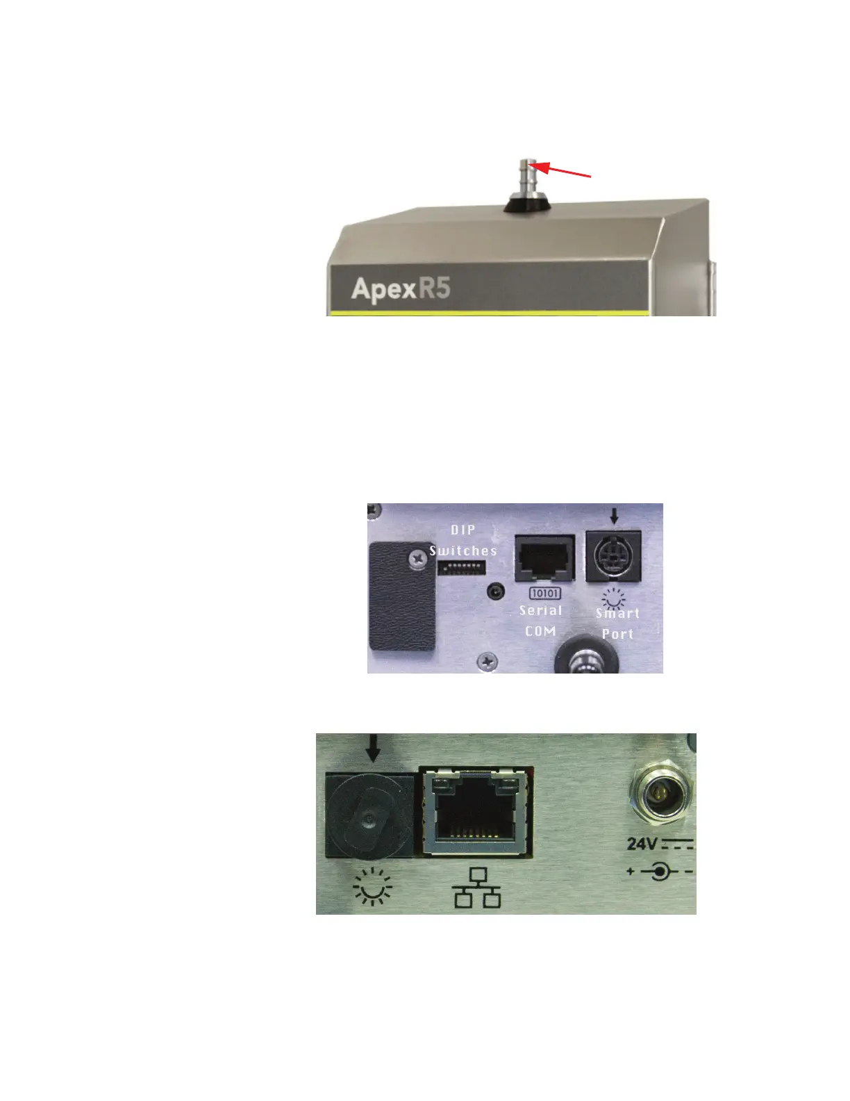
Connections The top of the instrument has one connection: the inlet nozzle for
sample input shown in Figure 7-6.
Figure 7-6 Connections on Top
The sensor can be used with a direct-mount 1.0 CFM isokinetic probe
or the probe can be attached via 1/4" ID tubing to a 1/4" barbed inlet
ISO Probe.
Figure 7-7 shows the bottom connections for the ApexRemote Serial
and Figure 7-8 shows the bottom connections for the ApexRemote
PoE.
Figure 7-7 Serial Instrument Connections
Figure 7-8 PoE Instrument Connections
Inlet
Nozzle
Ethernet
24VDC
Smart Port
with cover
 Loading...