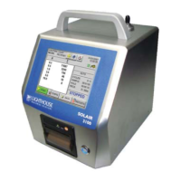
Setting up the Counter
248083389-1 Rev 4-17
5. The PC that will monitor or retrieve data from the instrument(s)
must be using the same subnet and gateway programmed on the
SOLAIR(s) network interface.
Configure
Device
Ethernet Port Configuration
This section is organized based on the cable used to perform the
SOLAIR programming.
Straight-through Cat5 requires a hub or switch and two straight-through
Cat5 cables. Cross-over Cat5 connects the PC directly to the SOLAIR
with no hub. Each will be explained separately. If troubleshooting is
required, the cross-over cable technique is easier to use in the field
because it requires fewer devices.
It cannot be stressed enough, however, that the instrument and PC be
configured using the same IP scheme (IP range, Default Gateway and
Netmask).
For troubleshooting outside of the LAN, it is suggested that the PC’s IP
address be used as the Default Gateway for both the PC and the
SOLAIR.
Frequently, it is necessary to change the SOLAIR Ethernet parameters
to allow for easier troubleshooting. When this is needed, make sure the
instrument is reprogrammed to its previous network settings before
reattaching to the LAN. Contact Lighthouse Technical Support at 800-
945-5905 (USA Toll Free) or 541-770-5905 (Outside of USA) or the
network administrator for additional information.
Straight-through Cat5 Setup:
Note:
Screens shown
are examples only. Data
displayed and command
responses may differ.
This section requires the PC, two straight-through Cat5 cables and the
hub or switch.
1. Connect one end of a straight-through Cat5 cable to the
SOLAIR’s Ethernet Port.
2. The other end of the Cat5 cable should plug into one port on the
hub or switch.
3. Attach another straight-through cable to the PC’s RJ45 receptacle
and an open port on the hub or switch.
4. Proceed to “Windows Telnet Programming:” on page 18.
 Loading...