TruScan 532 Single - Wavelength – Operators Manual Rev. No 02 Page 34 of 114
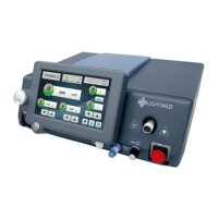
1. Emergency Stop Switch
This switch is provided a fast response shutdown of the laser system in the event of
some serious problem occurring. It is a RED color push switch that locks down when
pushed and in this position, all internal power will be removed. In order for system
to restore the power, the switch must be rotated to reset to the on position.
2. Key Switch
This key switch is the main power ON/OFF switch. The power can only be turned on
by inserting the key and rotating clockwise to the ON position. In the ON position
the key cannot be removed. The key should be stored in a safe and controlled place.
3. Laser Aperture (Port 1 / Port 2)
The Laser Delivery Unit’s fiber is connected here. The fiber connector must be fully
screwed in since there is an interlock switch which must engaged in order for the
Laser to function. No laser beam can be delivered through this aperture unless the
fiber is securely attached.
4. Delivery Key Connector
Each Delivery Unit has its own type of “Delivery Key” connector that must be fitted
to this socket so the microprocessor can recognize it. Always make sure the correct
Delivery Key is inserted for the LDU that is being used.
5. LIO Power
This connector is used to supply the power to the LIO Illumination. Whenever the
LIO is to be used the power must be connected in order to get suitable Illumination
before delivering the Laser Power.
6. Mains Power inlet
This socket is used to connect the Laser Console to the mains power. The input
voltage can be the range of 100 to 230 VAC as the internal PSU is an auto-ranging
module.
7. Footswitch Connector
This connector is fitted for the footswitch module which is the laser trigger firing
mechanism On/Off switch. This footswitch can be in wire or wireless module.
8. Joystick Connector
This connector is used to feedback or monitor joystick movement during normal
operation.
9. Remote Interlock Connector
 Loading...