WTR Series
Installation Instructions
WTR Installation & Maintenance Manual 330-15000 • Revision A • August
4.6 Setting the Mechanical Stops on the WTR
• If the WTR is shipped already installed on the valve, the Mechanical Stops should be set.
• If the WTR is not installed on the valve, the Mechanical Stops must be set after mounting.
The following instructions for setting the Mechanical Stops are based on the typical orienta-
tion (Position B) for most actuator applications: turn handwheel Clockwise to CLOSE and
Counterclockwise to OPEN.
Set or reset the stops as follows:
NOTE: Piece numbers correspond to piece numbers listed on Figure 6.1 or 6.2.
1. Set CLOSE Mechanical Stop Screw (piece #13/#22): loosen the Locking Nut (piece
#14/#23) and back off the Mechanical Stop Screw (piece #13/#22) to allow the valve to
travel to the fully CLOSED position.
2. Using the Handwheel, turn the valve to the CLOSE position. The valve must be fully
seated before setting the CLOSE mechanical stop.
NOTE: If the actuator is motor-operated, engage the Declutch Lever to put the electric
actuator in the manual mode. Use the electric actuator Handwheel for manual operation.
3. Rotate the Mechanical Stop Screw (piece #13/#22) in the clockwise direction until
contact is made with the Drive Sleeve (piece #4/#5).
CAUTION: When using an electric actuator, do not allow mechanical stops to be used
to torque against. Use the limit switch.
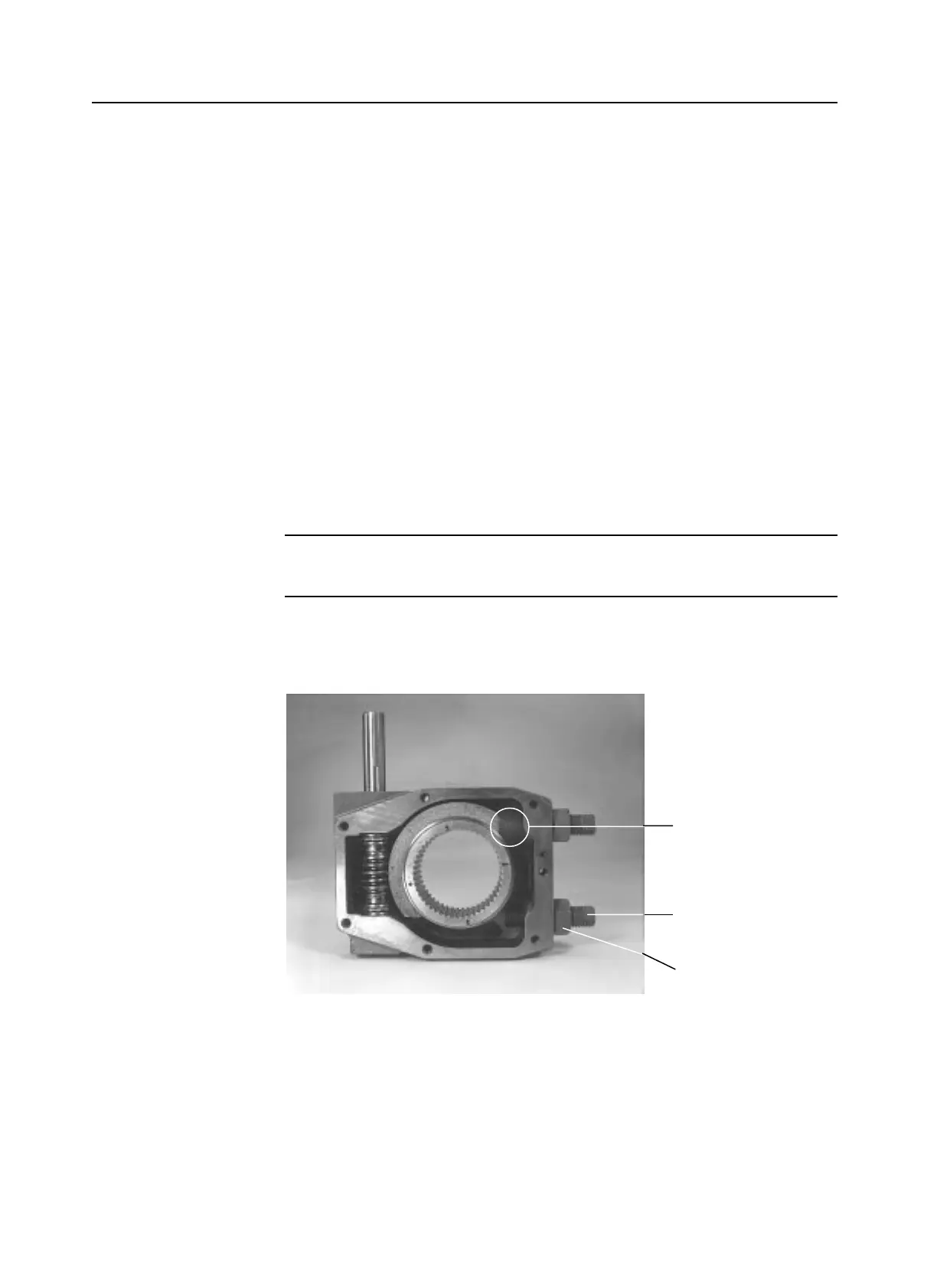
Figure 4.2 – Worm gear quadrant adjusted to contact with mechanical stops to set mechanical stop
screw position
4-6