Lifting Column LC3 IC | 21
Input/Output Specification Comments
Description Easy to use interface with integrated
power electronics (H-bridge)�
The column is speed controlled by means
of a 4-20 mA signal�
Proportional provides a wide range of
possibilities for customisation�
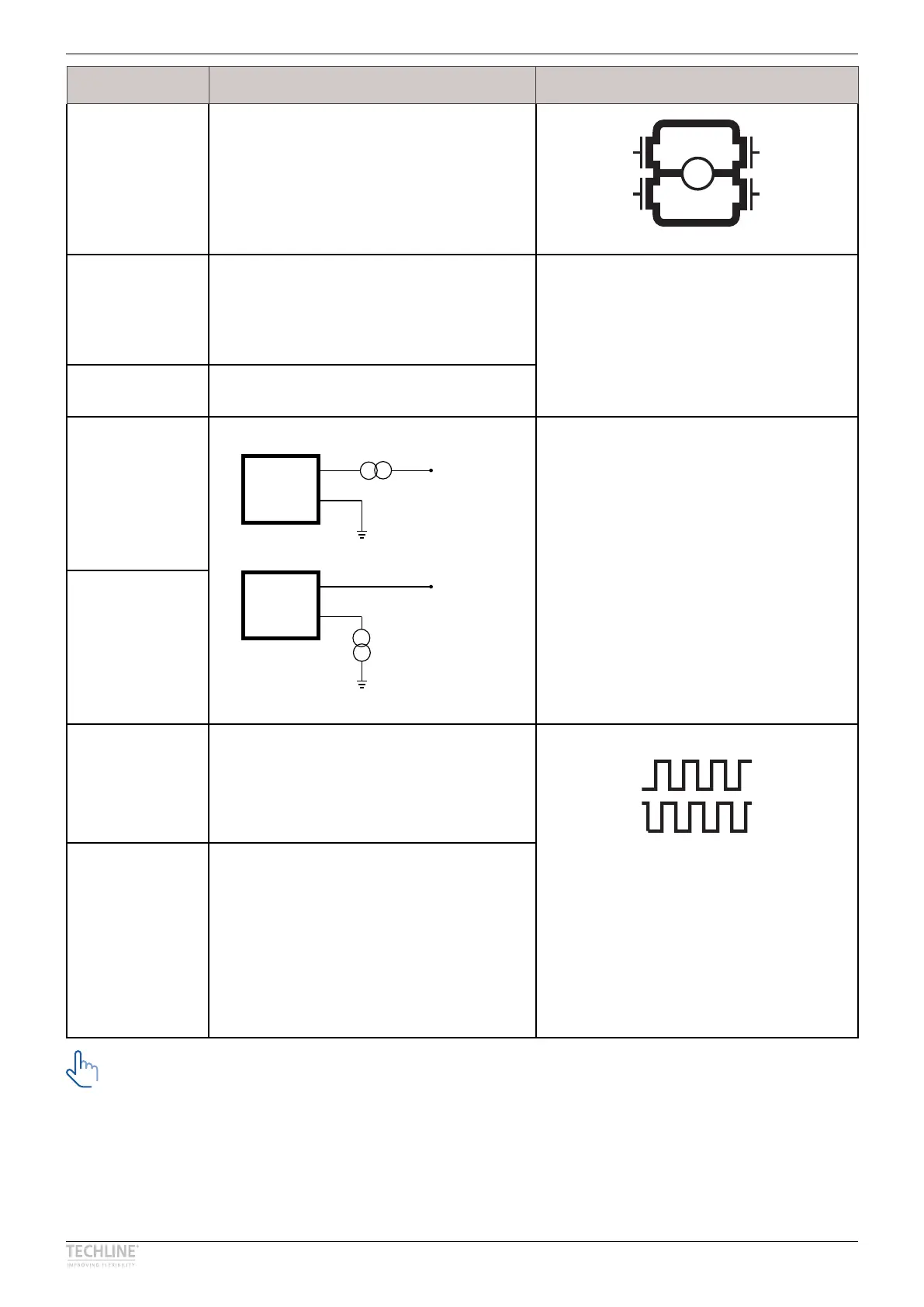
H-Bridge
M
Brown 24 VDC + (VCC)
Connect Brown to positive
24 V ± 10 %
24 V, max� 20 A - current limit @ 20 A
Note: Do not change the power supply
polarity on the brown and blue wires!
Power supply GND (-) is electrically
connected to the housing
Blue 24 VDC - (GND)
Connect Blue to negative
Black 4-20 mA: Sinking current with reference to power
GND (blue)
Common mode voltage: GND to V supply
Equivalent input resistance ≈ 135 ohm
Overcurrent protected, reverse voltage
protected
The column comes with a 0 ms soft stop
See paragraph Proportional (speed)
control for more details
Red
Yellow Hall A
Movement per each Hall pulse:
20 mm Pitch -> 0�303 mm/count
Hall output (PNP)
The Hall sensor signals are generated
by the turning of the column gearing�
These signals can be fed into a PLC
(Programmable Logic Controller)� In the
PLC the quadrature signals can be used
to register the direction and position�
Output voltage min� V
IN
- 2 V Current
output 12 mA Overvoltage on the motor
can result in shorter pulses�
Green Hall B
Movement per each Hall pulse
20 mm Pitch -> 0�303 mm/count
Prop
RED
BLACK
IN
V
Prop
RED
BLACK
IN
V
Current cut-offs should not be used as stop function! This might damage the column�
Current cut-offs should only be used in emergencies!
Current cut-off limits are not proportional with the load curves of the column� This means that the
current cut-offs cannot be used as load indicator�
There are tolerances on the spindle, nut, gear wheels etc� and these tolerances will have an influence
on the current consumption for the specific column�