Lifting Column LC3 IC | 10
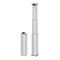
Built-in dimensions
146 0.5
146 0.5
101 0.5
101 0.5
43 0.5
163 1
129 1
146 1
4315
M10x1.5
30
M10
30
REP = STANDARD-SBU
B-B
SECTION A-A
MIN.90MIN.60
(M8) 146
(M6) 144 -146
(M5) 143 -146
(M4) 142 -146
M8
Drill-Max. 16
Thread-Max 14
M6
Drill-Max. 15
Thread-Max 13
M5
Drill-Max. 13
Thread-Max 11
M4
Drill-Max. 12
Thread-Max 10
½ S + 280mm
Created By Pamir Hamid 2022-07-07
Modified By Pamir Hamid 2022-07-11
SCALE : 1:5
Drawing No.: TEC-0001888
SECTION C-C
C
C
M10x1.5 M10x1.5
The minimum built-in dimension (BID) is 480 mm due to the design of the lifting column�
The tolerance for BID is +/- 1�5 mm
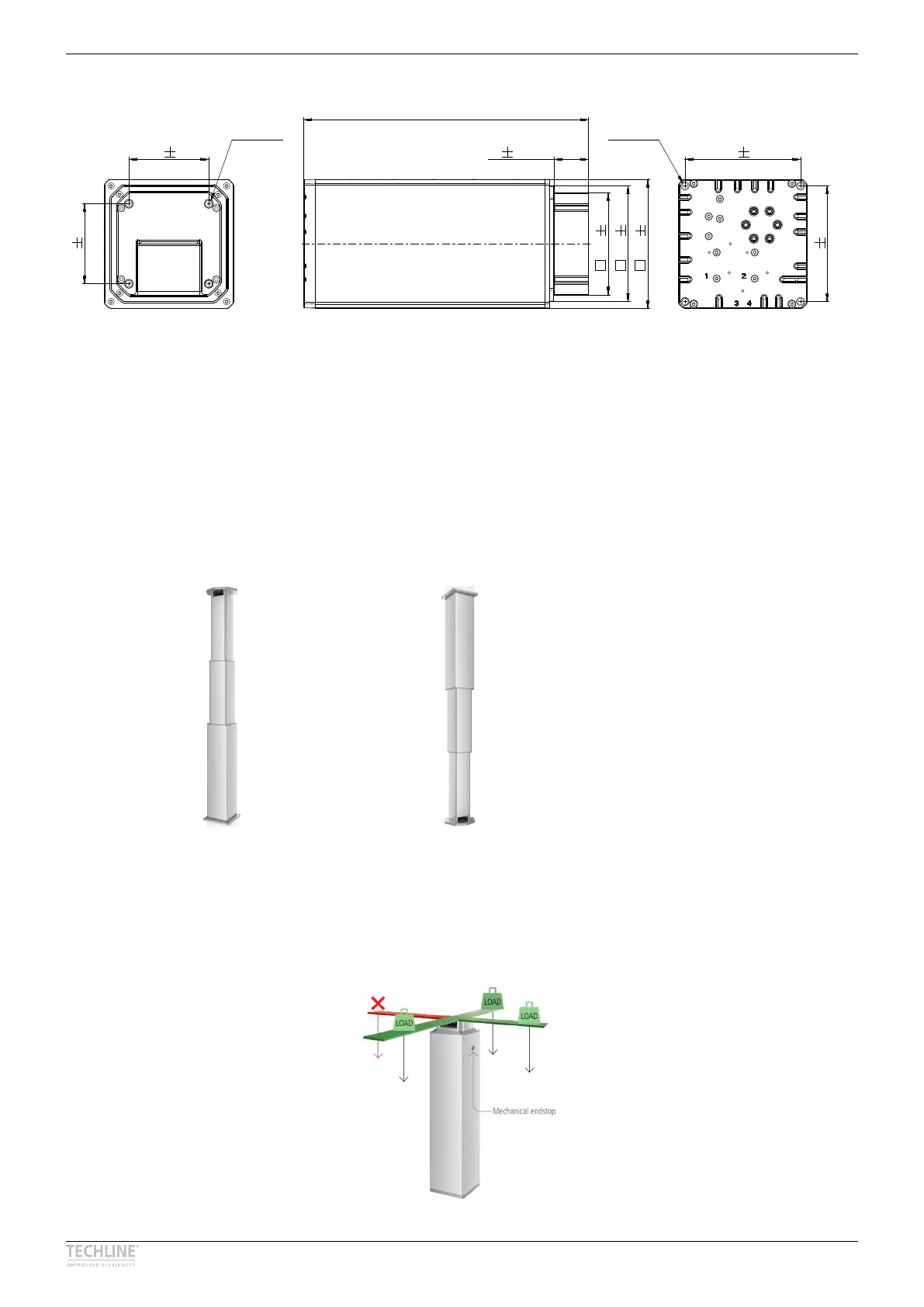
LC3 IC mounting guidelines
LC3 IC is for use in push applications and can be mounted in both directions – largest profile down or
largest profile up� The column can only be used for vertical movement -not for horizontal�
Top plate up Top plate down
Note: The cable outlet for motor connection is positioned at the top (smallest profile)
Mount the LC3 IC in the application using the 4x M10 mounting holes in both endplates�
If the column is to be used with a constant high off-center load, we recommend to install the constant
weight in one of the 3 ways illustrated by the green symbols� It is not recommended to install the weight on
the opposite side of the mechanical endstop as illustrated with the red symbol� This installation can create an
uneven movement and noise when the lifting column reaches the endstop position�