4
TRANSFORMER INSTALLATION
The Model TE5D transformer powers the DMC1 Master
Station. The Model TE2D transformer powers the optional
CD/MP3 Player. Both transformers are supplied in a small
metal enclosures that mount to the bottom of the wall
housing.
1. Run a minimum 14 AWG 120 VAC power cable (including ground)
from a dedicated 15-amp circuit breaker to the wall housing location.
The DMC1 requires a dedicated power source to assure there’s no
interference from other equipment. The ground is required for good
radio reception.
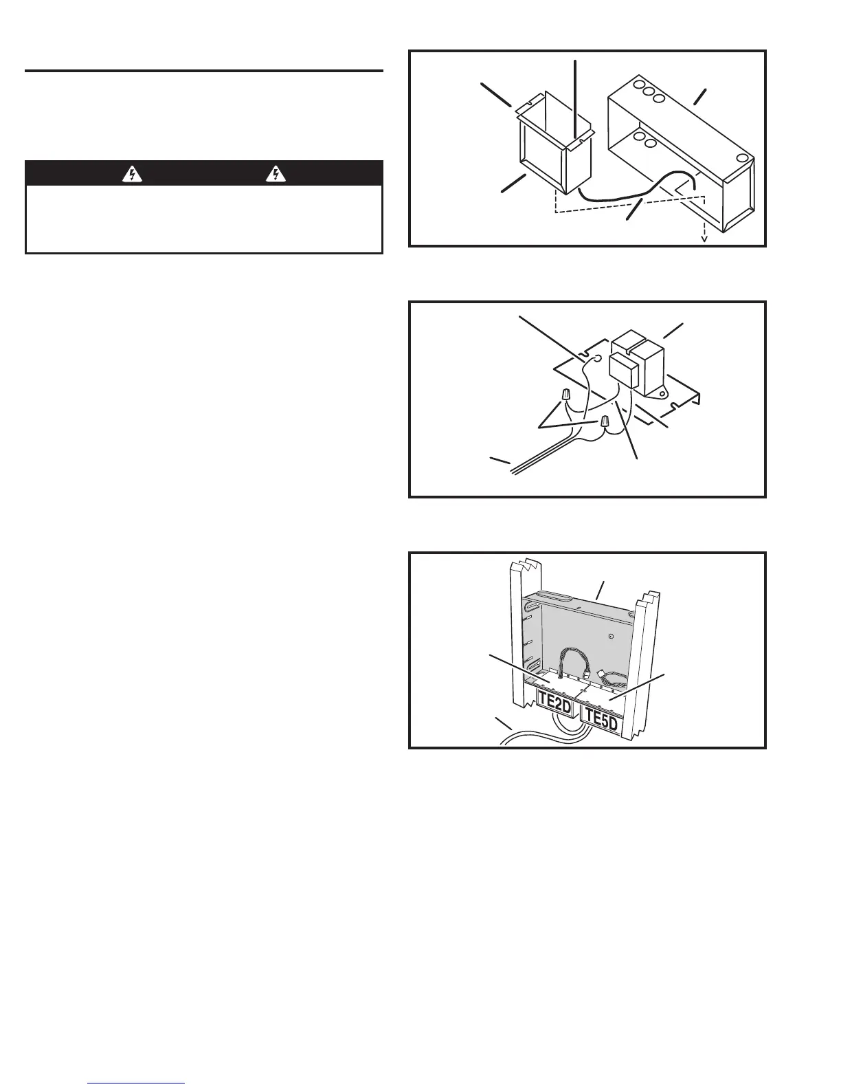
2. Slide the transformer enclosure(s) down into the rectangular
transformer mounting knockout(s) on the bottom of the wall housing
(see Figure 4).
3. If installing the second transformer for the CD Player option, cut a
1-1/2 foot length of power cable to loop between the two transformers.
Insert an end of the cable into each of the transformer enclosures
through the bottom knockout holes. Use wire nuts to connect the cable
to the TE2D transformer BLACK (HOT) and WHITE (NEUTRAL) input
wires. Connect the GREEN (GROUND) wire to the cable’s ground
conductor.
4. Route the incoming power cable into the TE5D transformer enclosure
through the bottom knockout hole. Use wire nuts to connect the
incoming power cable to the TE5D transformer BLACK (HOT) and
WHITE (NEUTRAL) input wires (and to the cable going to the TE2D
transformer if installed). Connect the GREEN (GROUND) wire to the
cable(s) ground conductor (see Figure 5).
5. Be sure all power cables entering the transformer enclosure(s) are
secured with cable strain reliefs.
6. Tuck the cables into the transformer enclosure(s) followed by the
transformer on its mounting plate. Secure the transformer(s) and
enclosure(s) to the wall housing with the screws supplied (see
Figure 6).
WARNING
ALL AC ELECTRICAL CONNECTIONS TO THE POWER SOURCE
AND THE TRANSFORMER(S) MUST BE MADE BY A LICENSED
ELECTRICIAN AND MUST OBSERVE ALL NATIONAL AND LOCAL
ELECTRICAL CODES
INSTALL TRANSFORMER
FROM INSIDE WALL HOUSING
120 VAC 60 HZ
FROM DEDICATED BREAKER
TRANSFORMER
ENCLOSURE
WALL HOUSING
(DMC1H SHOWN)
GROUND WIRE
(GREEN)
WIRE NUTS
DEDICATED
120 VAC 60 HZ
WITH GROUND
TRANSFORMER
BLACK (HOT)
WHITE (NEUTRAL)
TE5D TRANSFORMER
FOR MASTER
TE2D TRANSFORMER
FOR CD PLAYER
DMC1HC WALL HOUSING
120 VAC WIRING
FROM DEDICATED
CIRCUIT BREAKER
INSTALLATION EXAMPLE
FOR DMC1 WITH CD PLAYER
Figure 6. Completed Transformer Installation
Figure 5. Transformer Power Wiring
Figure 4. Transformer Enclosure Mounting