5
CAT-5 TO
STATIONS
AM ANTENNA WIRE
FM ANTENNA
DIPOLE
WALL HOUSING
(DMC1HC SHOWN)
AM FERRITE
FILTER
CEILING
PLATE
WHEN USING THE
DMC1H HOUSING,
ROUTE CABLES
THE SAME WAY!
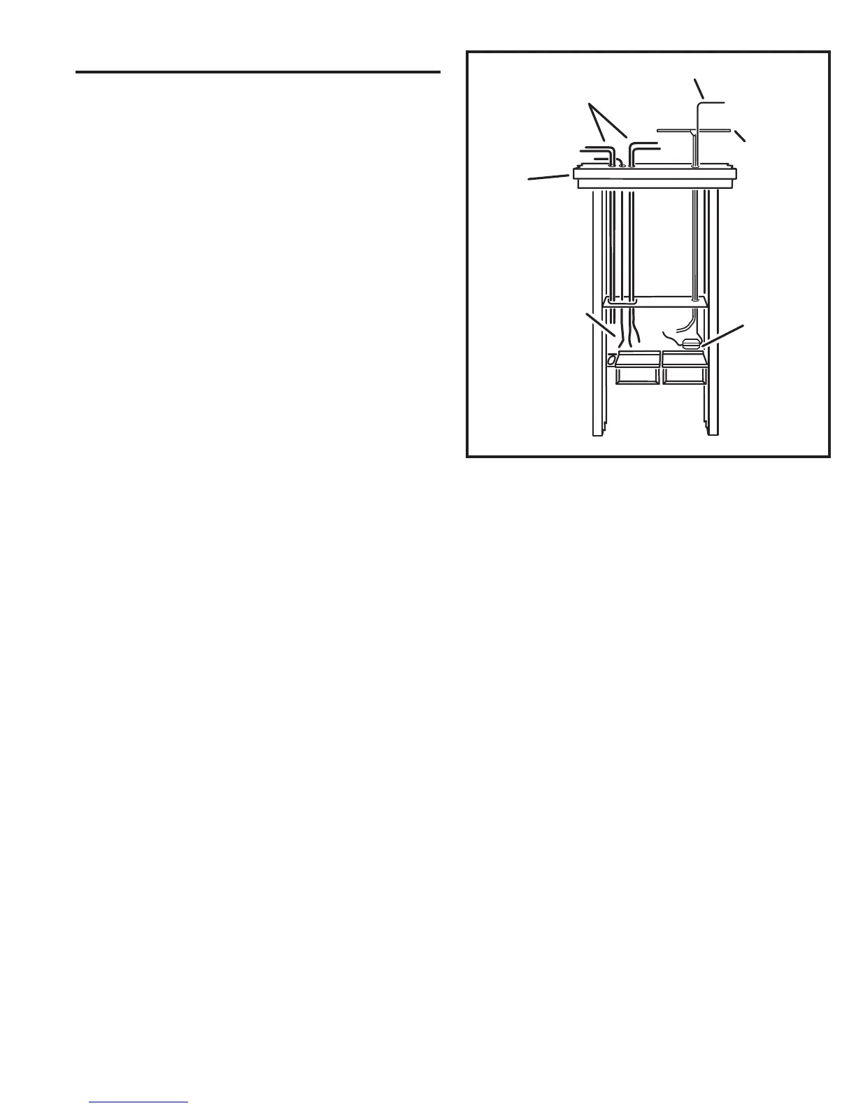
Figure 7. AM & FM Antenna Installation
ANTENNA ROUGH-IN
The DMC1 requires two antennas, one for AM and one for
FM reception. The AM antenna is a simple 25-foot length of
wire with an in-line ferrite fi lter to reduce interference. The
FM antenna is a 25-foot length of coax with a “T” shaped
wire dipole at one end that attaches between rafters in the
attic.
✔ IMPORTANT: Isolate the antenna leads from the intercom station
cables by running them through a separate hole in the ceiling plate
and through the right hole in the top of the wall housing. If grouped
together, the intercom station cables can shield the antenna leads
resulting in poor radio reception. Also keep the antenna leads away
from metal duct work and aluminum backed insulation, which also can
reduce reception.
1. Unroll and examine the 25-foot AM antenna wire. Find the end with
the ferrite fi lter (the small object with wire looped through it). The short
end of the wire from the fi lter attaches to the DMC1 AM antenna
terminal, the long end of the wire is the antenna that goes up into
the attic.
2. Fish the long end of the antenna wire up through the right hole in the
top of the wall housing, up the stud bay, through a hole in the ceiling
plate, and up into the attic. Pull all the wire through until the ferrite fi lter
lays inside the wall housing on the right side (see Figure 7).
3. Unroll and examine the FM antenna. The antenna is formed by
spreading the red and black wires at the end if the coax. The
terminal lug at the end of each wire is for screw mounting the wires
outstretched.
4. Fish the connector end of the antenna coax down through the hole in
the ceiling plate, down the stud bay, and into the hole on the top right
side of the wall housing. Leave about one foot of coax extending into
the wall housing (see Figure 7).
The antenna adjustment and fi nal installation will be
completed during the DMC1 Master Station fi nish-out.