Page 4 of 25 FA69372–2 English
Jun 2013
25
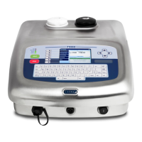
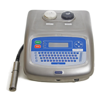
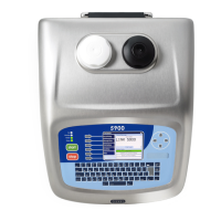
How To Install and Set Up the 5900 &
7900 Printer
Linx 5900 & 7900
One of two types of cable is supplied. The cables have the same specification but the colours
of the wires are different. The wire colours in the cable are as follows.
WARNING: THIS PRINTER MUST BE EARTHED/GROUNDED.
WARNING: THE PRINTER MUST BE ELECTRICALLY WIRED ONLY BY A QUALIFIED AND
COMPETENT ELECTRICIAN. LINX CANNOT ACCEPT RESPONSIBILITY FOR ANY INJURY TO
PERSONNEL OR DAMAGE TO MACHINERY CAUSED BY INCORRECT OR FAULTY WIRING.
1.7 Fit the printhead to the production line
You can set the printhead at any angle. Use a Linx printhead bracket to hold the printhead
correctly and prevent vibration—a number of bracket types are available.
The distance between the end of the printhead and the product is the ‘throw distance’. To
make sure that the print quality is good, set the throw distance to the recommended
distance shown in the table below.
WIRE COLOUR CONNECTION
Green-Yellow Green Earth/Ground
Blue White Neutral
Brown Black Live
Figure 2. Wire colours
Printhead Recommended distance
Midi 6 mm for a 25 Linear Speed message type,
12 mm for all other message types
Ultima 12 mm
Midi plus 12 mm
Ultima plus 12 mm
Mini The first digit in the name of the message type is the throw distance in
millimetres. For example ‘4T...’ indicates 4 mm. For the 5900, only 4 mm
and 8 mm throw distances are available. The 7900 printer also has a
12 mm throw distance available.
Micro (7900 only) 4 mm
Figure 3. Recommended throw distances