Page 6 of 25 FA69372–2 English
Jun 2013
25
How To Install and Set Up the 5900 &
7900 Printer
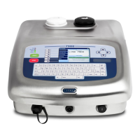
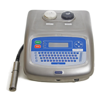
Linx 5900 & 7900
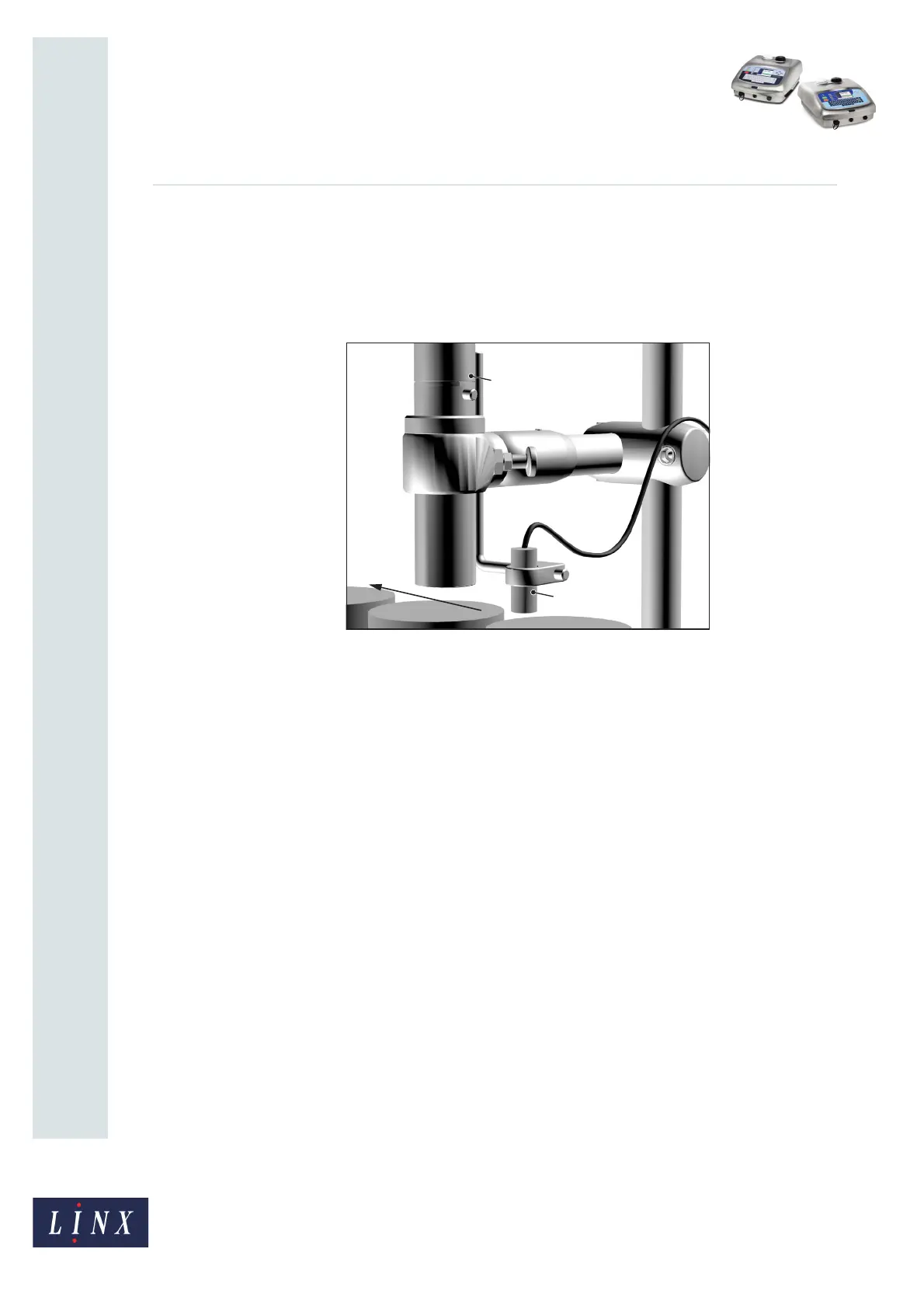
2 Product sensor setup
The Linx 5900 and 7900 printers can use a product sensor to detect the presence of the
product. Normally, the message is printed when the printer receives a trigger signal from
the product sensor.
Figure 5. Product sensor setup
Normally, the product passes the product sensor first, then the printhead. The distance
between the printhead and the product sensor must be less than the distance between the
products.
Figure 5 shows the product sensor (A) and the printhead (B). The arrow shows the direction
of movement of the product along the production line.
The Print Delay parameter controls the distance between the product sensor and the
printed message. For information on how to adjust the Print Delay, see the Linx 5900 & 7900
Quick Start Guide.
The following product sensor types are available from Linx:
• Fibre optic control unit, 5 m D-type
• Retro-reflective light beam, 5 m D-type
• Inductive switch, 5 m D-type
• Reflection light beam scanner, 5 m D-type
• Background suppression sensor, 5 m D-type
• Colour registration mark scanner, 5 m D-type
69120
A
B