8
lci1.com 574-537-8900 Rev: 03.21.19
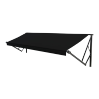
Solera
®
Universal Hardware
Manual Awning to
Solera 18V Power Awning
(For Aftermarket Applications)
CCD-0001267
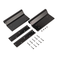
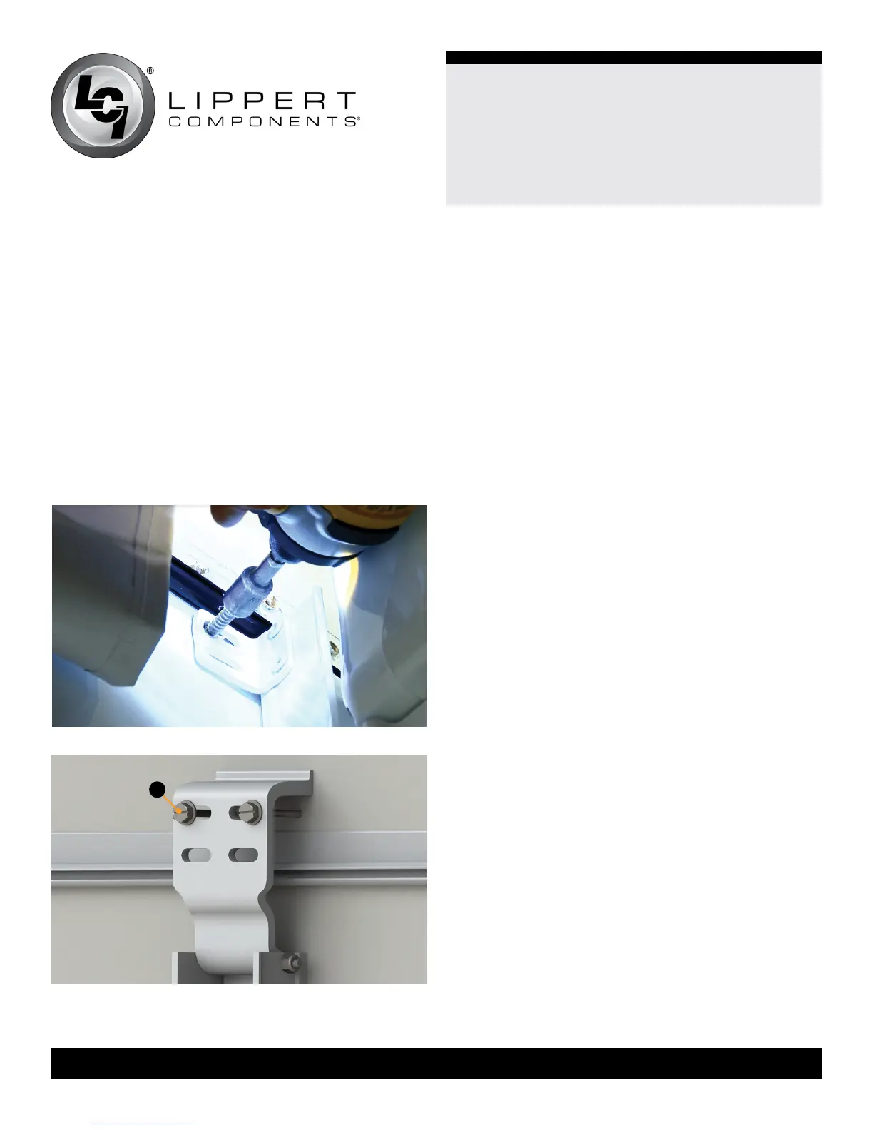
Fig.14
Fig.13
NOTE: Silicone sealant MUST be used on all screws and
holes to prevent water from inltrating the unit.
NOTE: Do NOT install fasteners to the lower and middle
sections of the wall mount arm at this time.
20. Re-install the cotter pin to the idler side end cap.
To properly align the hole for the cotter pin, it may be
necessary to slightly move the awning in or out using
the extend/retract switch. See Operation section in this
manual.
21. Repeat Steps 3-19 for the idler side of the awning,
skipping all cam lock instructions.
NOTE: Because the converted awning is approximately
2” wider than the previous awning, the support arm
assembly on the idler side will NOT align with the previous
holes. It is the customer’s responsibility to ll in/seal any
and all holes left on the unit after installation.
NOTE: The idler head does NOT have a cam lock. The
cotter pin is holding all the tension of the spring assembly.
NOTE: Be sure to handle the assembly with care and
always have a secure hold of the idler head.
22. Once the drive and idler side conversions are
complete, cut the nylon ties containing the support arm
assemblies.
23. Use the operation switch at the bottom of the drive
arm assembly to fully extend the awning. See Operation
section of this manual.
24. Remove the manual pull strap from the roll tube.
NOTE: If the drive arm’s battery is not charged, plug the
battery wires into the charger and the charger into a 110V
outlet. See Charging the Battery section in this manual.
The awning should become operational within ve minutes
after being plugged in.
25. Remove the wire covers on the drive support arm
assembly to expose the lower and middle sections of the
mount arm.
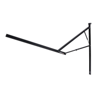
19. To secure the drive support arm assembly:
A. If using the original angle bracket on the new
support arm assembly, secure the upper section of the
drive mount arm to the unit with two of the provided
#14 - 10 x 1 ¼” screws (Fig.13).
B. If using the upper mounting bracket, attach the upper
mounting bracket (Fig.14A) of the assembled support arm
assembly, using the previously removed screws.
Go through the top holes of the upper mounting bracket
and into the pre-existing holes in the wall of the unit. All
screws supporting the awning assembly MUST have a
backer within the structure of the wall of the unit.
A