9
lci1.com 574-537-8900 Rev: 03.21.19
Solera
®
Universal Hardware
Manual Awning to
Solera 18V Power Awning
(For Aftermarket Applications)
CCD-0001267
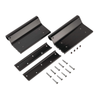
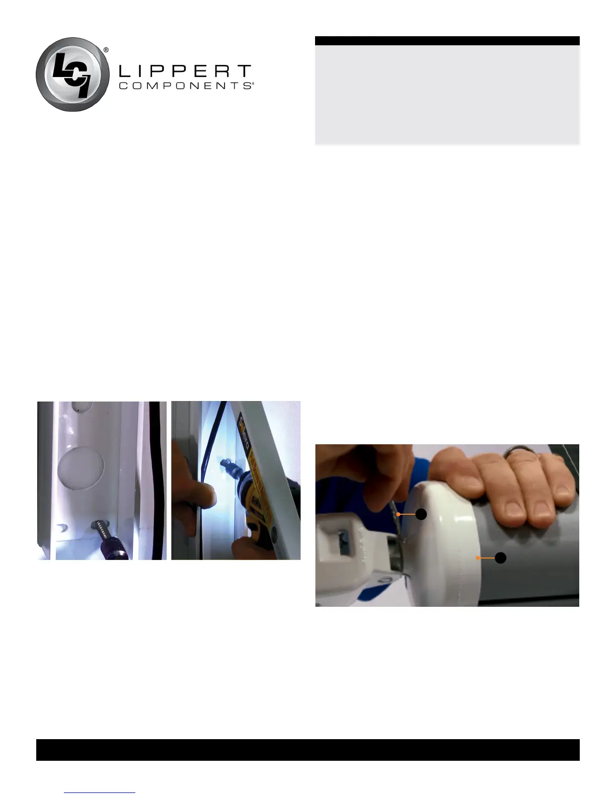
26. Secure the lower (Fig.15) and middle (Fig.16) sections
of the drive mount arm to the unit with the provided
#14 x 1 ¼” screws or rivets. Make sure the arm is square
on the unit wall. There will be two screws in the lower holes
and two screws in the middle holes.
NOTE: For units with berglass sidewalls, LCI requires the
use of rivets for securing the lower and middle sections of
the mount arm.
NOTE: All screws supporting the awning assembly MUST
have a backer within the structure of the wall of the unit.
NOTE: Silicone sealant MUST be used on all screws and
holes to prevent water from inltrating the unit.
27. Repeat Steps 25-26 for the idler mount arm.
28. Replace the wire covers.
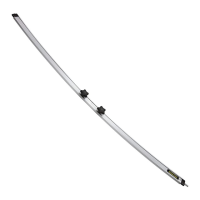
Fig.15
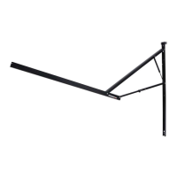
Fig.17
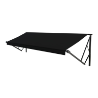
Carefree Manual Awning to Solera
18V Power Awning
NOTE: All screws supporting the awning assembly MUST
have a backer within the structure of the wall of the unit.
NOTE: This manual will refer to the “drive side” and “idler
side” throughout for various instructions. The “drive side”
is the right hand side of the awning when facing the awning
from the exterior of the unit. The “idler side” is the left
hand side of the awning when facing the awning from the
exterior of the unit.
1. Unlock the travel locks, move the cam lock to the roll out
position and extend the awning approximately 12”.
2. Insert a cotter pin (Fig.17A) into the end cap (Fig.17B) at
each end of the awning.
NOTE: Some Carefree systems do not have a hole on the
drive end cap for the cotter pin. In this instance, the cam
lock MUST remain in the roll out position until it is time to
release the tension in the springs.
Fig.16
A
B