5
lci1.com 574-537-8900 Rev: 03.21.19
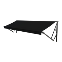
Solera
®
Universal Hardware
Manual Awning to
Solera 18V Power Awning
(For Aftermarket Applications)
CCD-0001267
Conversion
Dometic Manual Awning to Solera 18V Power
Awning
NOTE: All screws supporting the awning assembly must
have a backer within the structure of the wall of the unit.
NOTE: This manual will refer to the “drive side” and “idler
side” throughout for various instructions. The “drive side” is
the right hand side of the awning when facing the awning
from the exterior of the unit. The “idler side” is the left
hand side of the awning when facing the awning from the
exterior of the unit.
When converting a Dometic Manual Awning to a Solera
18V Power Awning, the converted awning will be
approximately 2” wider than the initial awning. Be sure
there are no obstructions that may interfere with the
installation of the support arm assemblies PRIOR to
beginning the conversion process.
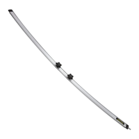
1. Unlock the travel locks, move the cam lock to the roll out
position and extend the awning approximately 12”.
2. Insert a cotter pin (Fig.5C) into the end cap (Fig.5A)
at each end of the awning.
3. On the drive side of the awning, and with an assistant
holding the roll tube, use a ⁄” socket to remove the
bolt securing the drive head (Fig.5B) to the support arm
(Fig.5D).
A B
C
D
Fig.4
Fig.5
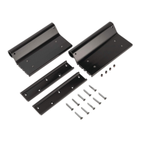
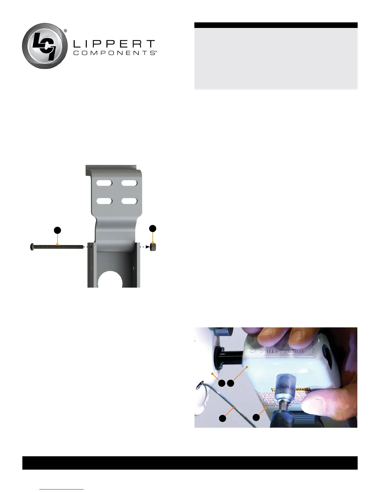
3. Insert the provided #10 - 32 x 2 ½” screw (Fig.4A)
through the support arm assembly, through the upper
mounting bracket bolt guide and into the other side of the
support arm assembly.
4. Attach the provided #10 - 32 Nylon Locking nut to the
bolt to hold the bracket in place (Fig.4B).
5. Repeat steps 1-4 for the other support arm assembly.
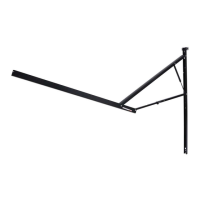
6. Set the support arm assemblies aside and proceed with
the Conversion section.
NOTE: Once the support arm assemblies with the new
upper mounting brackets are ready to be installed, use
the same holes located in the unit wall that were left when
removing the old arm assemblies.
A
B