M & MA Series Meters
25
Get the latest PDF manual:
https://www.lcmeter.com/resources/technical/manuals
Mobile/online version of this manual:
https://www.lcmeter.com/manuals
2. Remove the dust cover screws with a 5/16" wrench or slotted screwdriver.
3. Remove the dust cover.
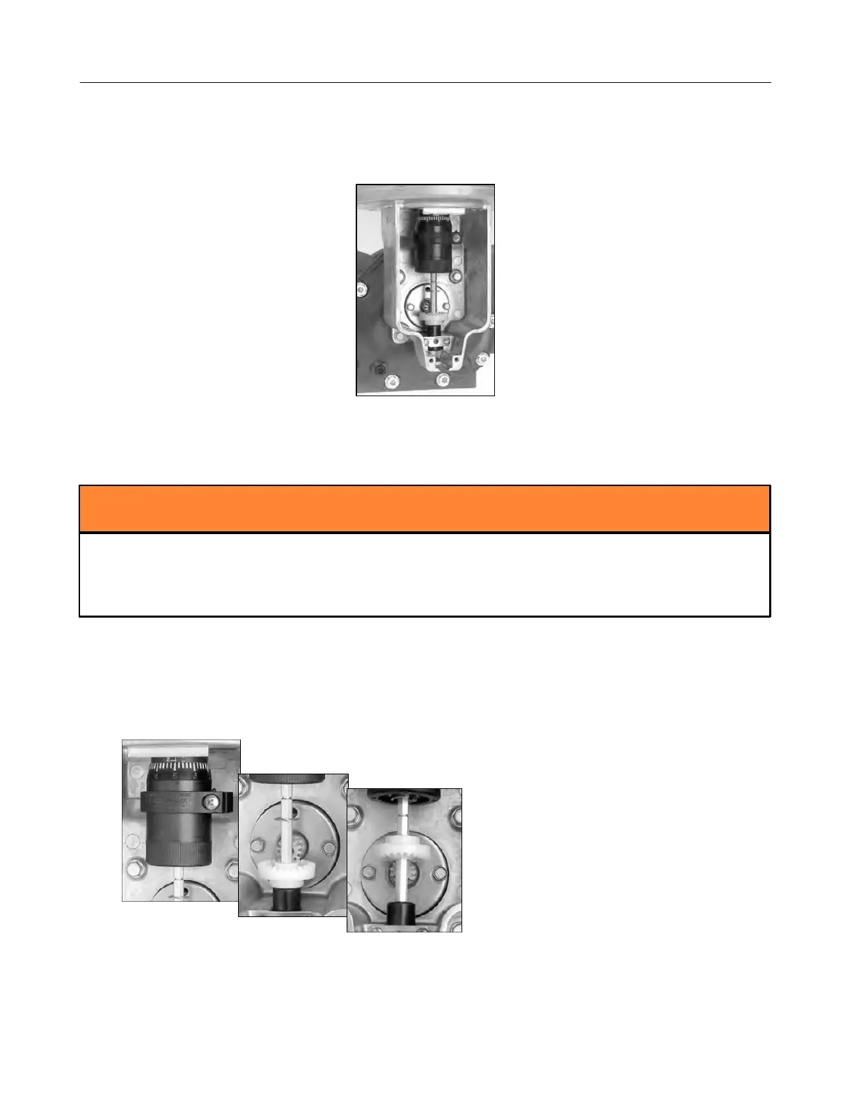
Servicing the Adjuster and Adjuster Drive Assembly
Remember to Reassemble to the Original Position
Make sure to return the adjuster drive gear to its original position when reinstalling or the
meter counter will run backwards. The gear will be set either below or above the packing
gland pinion.
Follow this procedure to remove the adjuster and adjuster drive assembly:
1. Record the adjuster micrometer setting and note the adjuster drive gear position.
2. Use a standard screwdriver to loosen (or remove) the two retaining spring screws.