EasyManuals Logo

Liquid Controls M Series User Manual

Liquid Controls M Series
48 pages
To Next Page IconTo Next Page
To Previous Page IconTo Previous Page
Page #34 background imageLoading...
Page #34 background image
M & MA Series Meters
34
Get the latest PDF manual:
https://www.lcmeter.com/resources/technical/manuals
Mobile/online version of this manual:
https://www.lcmeter.com/manuals
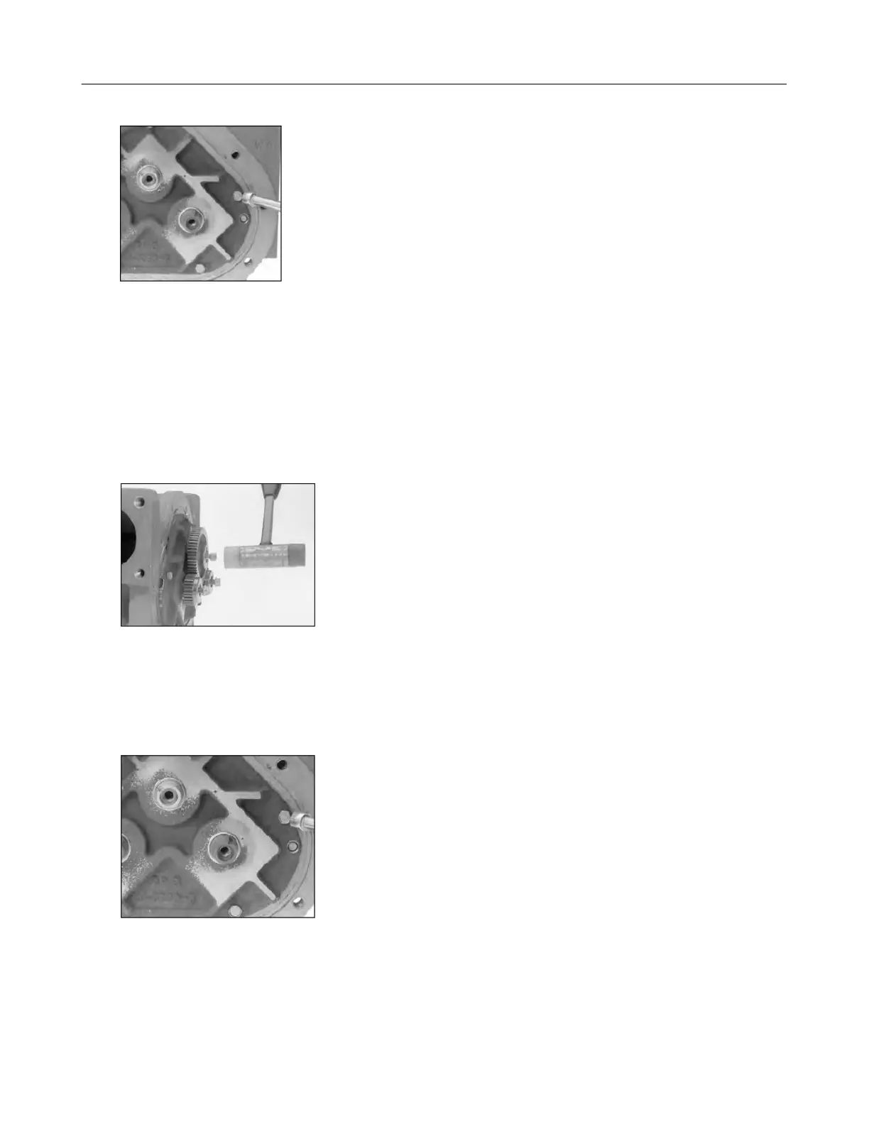
3. With a plastic or non-metallic mallet, tap on the heads of the screws on the rotor ends
lightly and equally, slowly driving the rotors off of the rotor gears. As you tap on the
screws, the rear bearing plate and the rotor assembly will separate from the housing.
NOTE: For carbon insert bearing plates, remove the rear plate first and then each rotor
as it is hand supported.
4. Use the bearing plate wrench (or a socket driver) to remove the screws that hold the
front bearing plate to the meter housing. The number of screws will vary depending on
meter size.

Other manuals for Liquid Controls M Series

Questions and Answers:

Question and Answer IconNeed help?

Do you have a question about the Liquid Controls M Series and is the answer not in the manual?

Liquid Controls M Series Specifications

General IconGeneral
Temperature Range-40°F to +160°F (-40°C to +71°C) standard, extended ranges available
Materialsstainless steel
TypePositive displacement flow meter
Fluid Compatibilityfuels, oils, and chemicals
Sizes6"
Output OptionsPulse

Related product manuals