M & MA Series Meters
38
Get the latest PDF manual:
https://www.lcmeter.com/resources/technical/manuals
Mobile/online version of this manual:
https://www.lcmeter.com/manuals
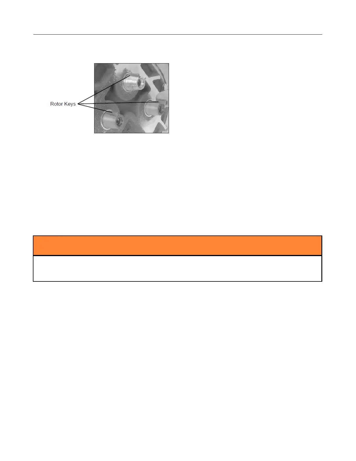
Timing the rotor gears
Before putting the meter into service, the rotors must be timed. Rotors are timed by lining up
timing marks stamped onto the face of the gears. The timing mark on the blocking rotor gear is
stamped on a gear tooth. The timing mark on the displacement rotor gears is stamped on a
space between two gear teeth. You may need to remove the gears and reposition them
several times to line up the timing marks correctly.
For step 6 in the following procedure, tighten the gear screws to the torque specification
given in the Torque Chart section below.
Follow this procedure to time the rotor gears:
1. Slide the blocking rotor gear over the tapered blocking rotor end and turn it until the
timing mark is in position to line up with the timing mark on the right displacement rotor
gear. Slide the right displacement rotor gear over the tapered end of the rotor so that the
timing mark lines up with the blocking rotor gear timing mark.
2. Turn the blocking rotor gear (turn the right displacement rotor gear with it) until the timing
mark is in position to line up with the timing mark on the left displacement rotor gear.
Slide the left displacement rotor gear over the tapered end of the rotor so that the timing
mark lines up with the blocking rotor gear timing mark.