LXC31X0/LXC93X0 Generator controller user manual
Dongguan Tuancheng Automation Equipment Co.,LTD.
LXC31X0/LXC39X0 User Manual Dongguan Tuancheng Automation Equipment Co.,LTD.
: T:+86 769-23162896 : F:+86 769-23166296 :www.lixise.com Page 27 of 28
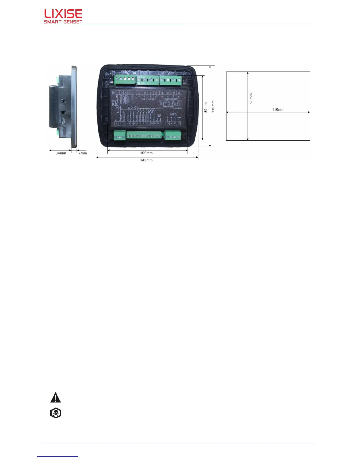
10.2. Overall dimension and panel cutout
Product size
:
Panel Cutout
:
LXC31X0/LXC39X0 series controller can suit for widely range of battery voltage DC(8~35)V.Negative
of battery must be connected with the engine shell. The diameter of wire which from power supply to
battery must be over 1.5mm. If floating charge configured, please firstly connect output wires of
charger to battery’s positive and negative directly, then, connect wires from battery’s positive and
negative to controller’s positive and negative input ports in order to prevent charge disturbing the
controller’s normal working.
Speed sensor is the magnetic equipment which be installed in starter and for detecting flywheel teeth.
Its connection wires to controller should apply for 2 cores shielding line. The shielding layer should
connect to No. 1 terminal in controller while another side is hanging in air. The else two signal wires
are connected to No.1 and No.17 terminals in controller. The output voltage of speed sensor should
be within AC(1~24)V (effective value) during the full speed. AC12V is recommended (in rated speed).
When install the speed sensor, let the sensor is spun to contacting flywheel first, then, port out 1/3 lap,
and lock the nuts of sensor at last.
Output And Expansion Relay
All outputs of controller are relay contact output type. If need to expand the relays, please add
freewheel diode to both ends of expand relay’s coils (when coils of relay has DC current) or, add
resistance-capacitance return circuit (when coils of relay has AC current), in order to prevent
disturbance to controller or others equipment.
LXC31X0/LXC39X0 series controller must be connected to outside current transformer. And the
current transformer’s secondary side current must be 5A. At the same time, the phases of current
transformer and input voltage must correct. Otherwise, the collected current and active power maybe
not correct.
CAUTION
!
ICOM port must be connected to negative pole of battery.
WARNING! When there is load current, transformer’s secondary side prohibit open circuit.
 Loading...