8
Instruction Manual
SECTION 3 - INSTALLATION
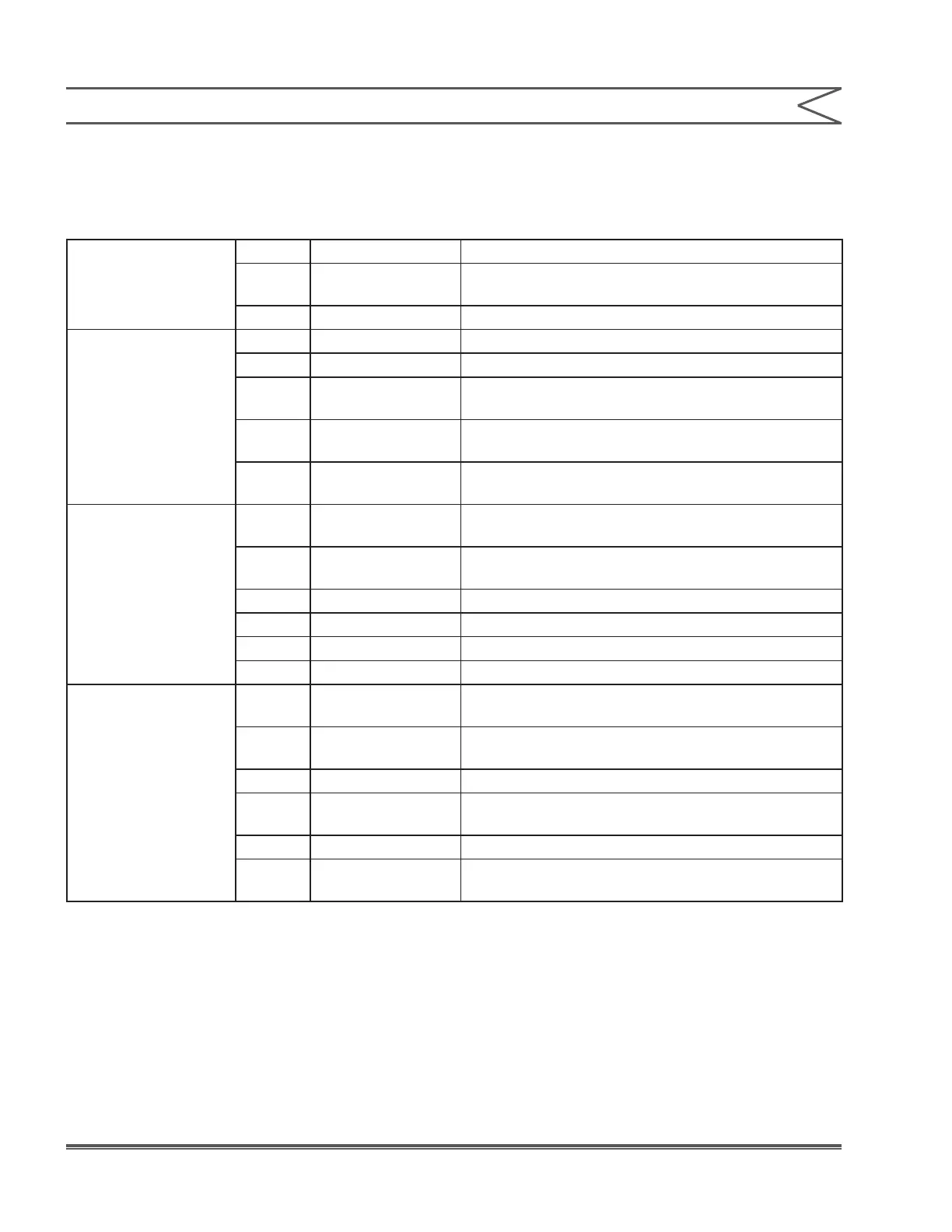
3.5.2 Terminal Board Signal Description
Terminal blocks are TB1-TB4 from left to right, and
Pin 1 is at the bottom of each terminal block.
TB1 Terminal Strip
TB1 Pin 1-Pin 3 Earth connection (one for input power connection)
TB1 Pin 4-Pin 9
Neutral power connection (one for input power
connection)
TB1 Pin 10 AC Mains live input
TB2 Terminal Strip
TB2 Pin 1 Form A contact closed when Pump B (base) is ON
TB2 Pin 2 Form A contact closed when Pump A (acid) is ON
TB2 Pin 3-4
Form C contact activated, (if programmed) when
pH is within programmed limits (solenoid pump)
TB2 Pin 5-6
Form C contact activated when Alarm Setpoint 2
exceeded (powered output contacts)
TB2 Pin 7-8
Form C contact activated when Alarm Setpoint 1
exceeded (powered output contacts)
TB3 Terminal Strip
TB3 Pin 1-2
Opto isolated input - low or short stops pumps
(OFF on display)(Remote OFF)
TB3 Pin 3-4
Opto isolated output - low when alarm condition
exists
TB3 Pin 5-6 Opto isolated output - pulse train to drive Pump A
TB3 Pin 7-8 Opto isolated output - pulse train to drive Pump B
TB3 Pin 9-10 Spare, not programmed
TB3 Pin 11-12 Spare, not programmed
TB4 Terminal Strip
TB4 Pin 1-2
Opto isolated input - ow switch input
(add jumper if no ow switch is used)
TB4 Pin 3-4
Opto isolated input - level switch input
(add jumper if no level switch is used)
TB4 Pin 5-6 Spare, not programmed
TB4 Pin 7-8
Temperature input (from platinum RTD probe)
(polarity sensitive)
TB4 Pin 9-10 Power voltage source for preamp
TB4 Pin 11-12
4-20 mA output proportional to pH
(programmable limits) (optional) (polarity sensitive)
 Loading...