3Instruction Manual
SECTION 3 - INSTALLATION
3.1 PRE-INSTALLATION
BE SURE THAT THE UNIT HAS A
PLUG AND VOLTAGE CODE
COMPATIBLE WITH THE POWER SOURCE THAT YOU INTEND
TO USE.
3.2 ENVIRONMENT
The housing is corrosion and spray resistant but
should not be subjected to excessive spray or
ambient temperature over 122°F (50°C). Never
immerse the unit.
3.3 INSTALLATION
The LIQUITRON™ DP5000 Controller should
be mounted on a solid, stable surface. pH
adjustment pumps should be installed following the
manufacturer’s recommendations. For installations
requiring longer cables, consult your distributor.
The electrode installation will vary, depending on
the process used. In general, the temperature
electrode and pH electrode should be mounted
together, and placed far enough downstream from
the source of pH adjusting solution that sufcient
mixing may occur, but close enough to eliminate
hydraulic lag time of response. Refer to the typical
installation diagrams on the following page.
3.4 MOUNTING THE ELECTRONIC
ENCLOSURE
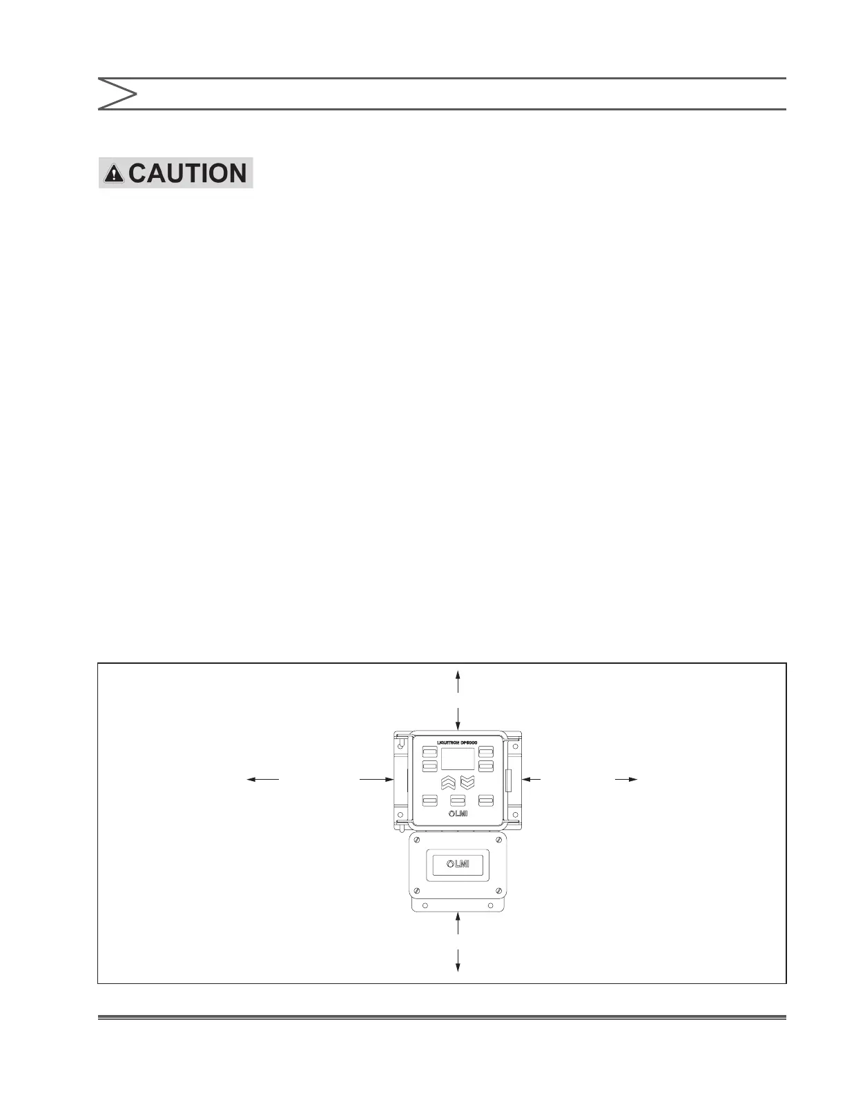
The LIQUITRON™ DP5000 control module is
supplied with integral wall mounting anges. It
should be hung with the display at eye level, on a
vibration-free structure, in a location where liquids
will not be splashed on it. All four (4) top-mounting
holes should be used for structural stability. The
control module requires the following clearances:
2” (51mm)
10” (254mm)
4” (102mm)
8” (203mm)
Figure 2. Minimum Clearances
 Loading...