5Instruction Manual
3.5 ELECTRICAL INSTALLATION
3.5.1 Electrical Connections
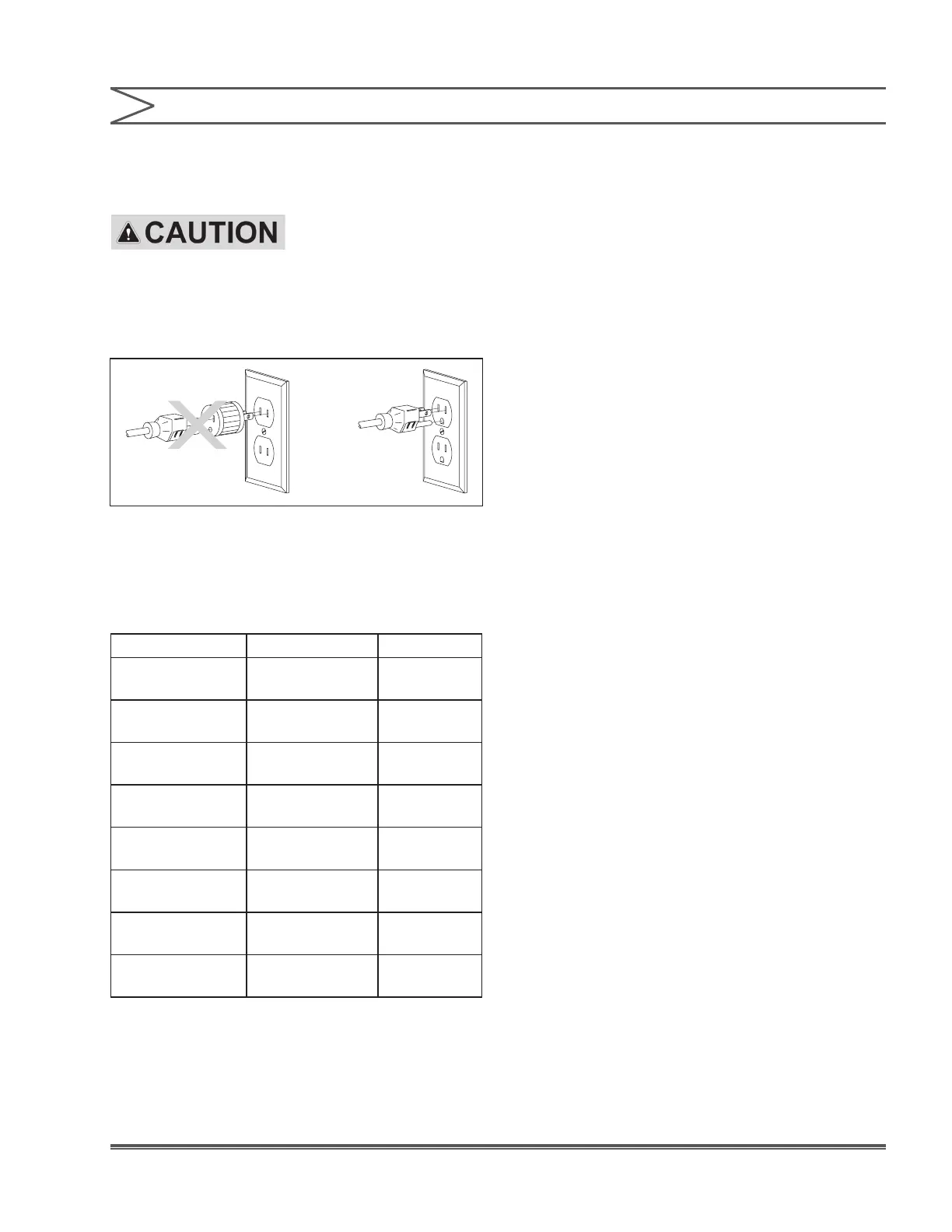
TO REDUCE THE RISK OF
ELECTRICAL SHOCK, THE
CONTROL OR METERING PUMP MUST BE PLUGGED INTO A
GROUND OUTLET WITH RATINGS CONFORMING TO THE DATA
ON THE CONTROL PANEL. IT MUST BE CONNECTED TO A
GOOD GROUND. DO NOT USE ADAPTERS. ALL WIRING MUST
CONFORM TO LOCAL ELECTRICAL CODES.
SECTION 3 - INSTALLATION
INCORRECT CORRECT
Electrical installation of the DP5000 Series pH
Controllers consists of plugging the control module
into a proper line outlet. Based on model number,
the following voltages and receptacles are required:
Model Number voltage Receptacles
DP5000-1A
DP5000-1B
115 V, 60 Hz USA Cord
DP5000-01A
DP5000-01B
115 V, 60 Hz No Cord
DP5000-2A
DP5000-2B
230 V, 60Hz USA Cord
DP5000-02A
DP5000-02B
230 V, 50/60Hz No Cord
DP5000-3A
DP5000-3B
230 V, 50 Hz DIN Cord
DP5000-5A
DP5000-5B
230 V, 50 Hz UK Cord
DP5000-6A
DP5000-6B
230 V, 50 Hz
AUS / NZ
Cord
DP5000-7A
DP5000-7B
230 V, 50Hz
SWISS
Cord
Connect the pH adjustment pump(s) to the
terminal strip for ‘ON / OFF’ control (connect to
receptacles directly for 115 V models) or to cables
for ‘PROPORTIONAL’ control. Connect the pH
electrode to the BNC connector on the right side
of the control module. Take care not to twist or
strain the wires. If equipped, connect the ATC cable
(1000 Ω at 32°F (0°C)) through the cable gland
below the BNC connector to the terminal strip. You
may optionally connect an alarm, solenoid, ow
switch and low level switch. You may also connect
the mA connections (with the option tted). The
± 5 V supply for electrode pre-amplication is also
accessed on the terminal strip. There is a 500 Ω
maximum resistance for 4-20 mA option (refer to
Figures 4 and 5).
 Loading...