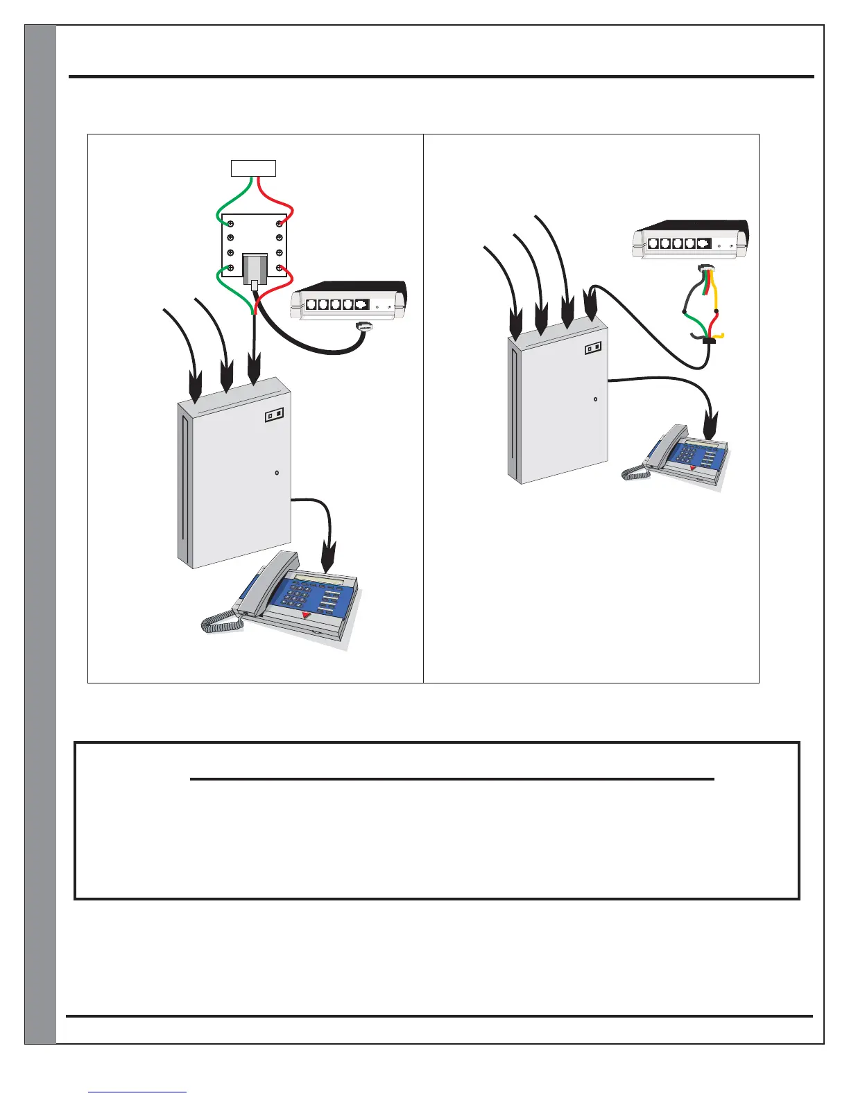
KSU/PBX Installation Diagram
Page 11
KSU
Phone System
KSU
Phone System
Using one of the existing lines
Using the and an
availble C/O port
TeleDoorBell
Eg:
3-Line
system
Eg:
3-Line
system
Line 1
Line 1
Line 2
Line 2
Line 3
Line 3
Line 4
TeleDoorBell
Line1 / Line2 / Line 3 with TeleDoorBell
Line1 / Line2 / Line 3 / Line4 TeleDoorBell
* Note: In this installation the will
function properly with the exception of being able
to monitor the door speaker. The speaker will
only be active when the button is pressed. To be
able to monitor your door speaker any time you
will require a TBG-1 accessory module. (Page 9)
TeleDoorBell
OUT OUT
IN IN
RJ31X
(CA38A)
Data Jack
(Not supplied)
Tip
Ring
Phone System must be programmed for extensions to ring.
Consult your KSU/PBX phone system manual for instructions
Black
Green
Red
Yellow
Spk/Rly#4 Spk/Relay#3 Spk/Relay#2 Spk/Relay#1 Tele Line In & Out
Power Plug
A202CR & A204CR
Spk/Rly#4 Spk/Relay#3 Spk/Relay#2 Spk/Relay#1 Tele Line In & Out
Power Plug
A202CR & A204CR
Grey
Red
Brown
Green
PLEASE VERIFY THAT YOUR TELEPHONE SYSTEM COMPLIES WITH A TYPICAL 95
VOLTS RMS @ 20 Hz RING. IF INSTALLED WITHOUT VERIFICATION
TELEPHONE EQUIPMEN
, THIS PRODUCT
MAY CAUSE DAMAGE TO T. IF YOUR TELEPHONE SYSTEM
DOES NOT MEET THE ABOVE REQUIREMENTS PLEASE CONTACT LOGENEX
INNOVATIONS INC. FOR FURTHER INFORMATION.
NOTICE