20
• The kitchen area should be dry and equipped with sufficient
ventilation.
• When installing the oven, easy access to all control elements
should be ensured.
• This is a built-in oven. Coating or veneer used on fitted furniture
must be applied with a heat-resistant adhesive (100°C). This
prevents surface deformation or detachment of the coating.
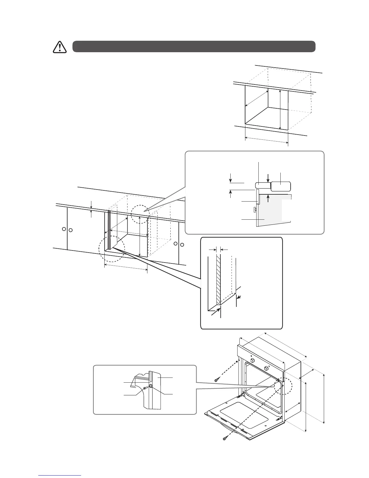
• Ensure that the cabinet is designed to be used with built-in ovens.
• Ensure you have the dimensions given in the diagram for the oven to
be fitted. You can use either cabinet 1 or cabinet 2 cut-out sizes.
The mains connection for this product must have an all pole disconnection provided in the fixed wiring in
accordance with the local wiring regulations.
To avoid any potential hazard, you must follow these instructions when you install your appliance.
575mm
600mm
565mm
Cabinet 1
• Once the oven is installed, fix with the two screws in the
places shown in the diagram.
Min. 40mm (the wooden
part can be extended up
to cut-out depth)
605mm
Min 25mm
595mm
565mm
605mm
Cabinet 2
Min.50mm
Countertop
Distance between
countertop and
control panel
Distance between
countertop and
top panel of built-
in oven
Built-in
Oven
Control
Panel
Built-in Hob
560mm
595mm
560mm
555mm
585mm
595mm
Front Frame
Spacer
Wooden
part
Mounting
Screw
* All images are for indication only; please refer to your individual unit for actual item.
LBMULB13_IB_130620_chris.indd 20 20/6/13 11:41 AM