Revision 1 – 04.12.2015 18/28
M1-9 ANALOG OUTPUT
This menu is visualized only if the safety pressure transducer has been configured in the menu Compressor setup
(parameter C18 different from 0).
The analog output is determined by a PID calculation.
The analog output can be eventually connected to the electrical motor inverter or fan motor inverter. Parameter C18 must
be set 1 for electric motor or 2 for fan motor.
In case of electric motor the regulation is made by the pressure. The setpoint of the PID calculation is placed in the middle
of the interval between start pressure WP3 stop pressure WP4. Example: WP3=7bar and WP4=8bar, setpoint will be 7.5bar
and PID will try to keep the working pressure around such reference value by increasing the inverter output (frequency as
well) in case the pressure is lower than the set and decreasing in case the pressure is higher.
In case of the fan motor the regulation is made by the temperature. The sepoint of the PID calculation is the value set on
WT3 (fan start). PID will try to keep the air end temperature around such reference value by increasing the inverter output
(frequency as well) in case the temperature is higher than the set value and decreasing in case the temperature is lower.
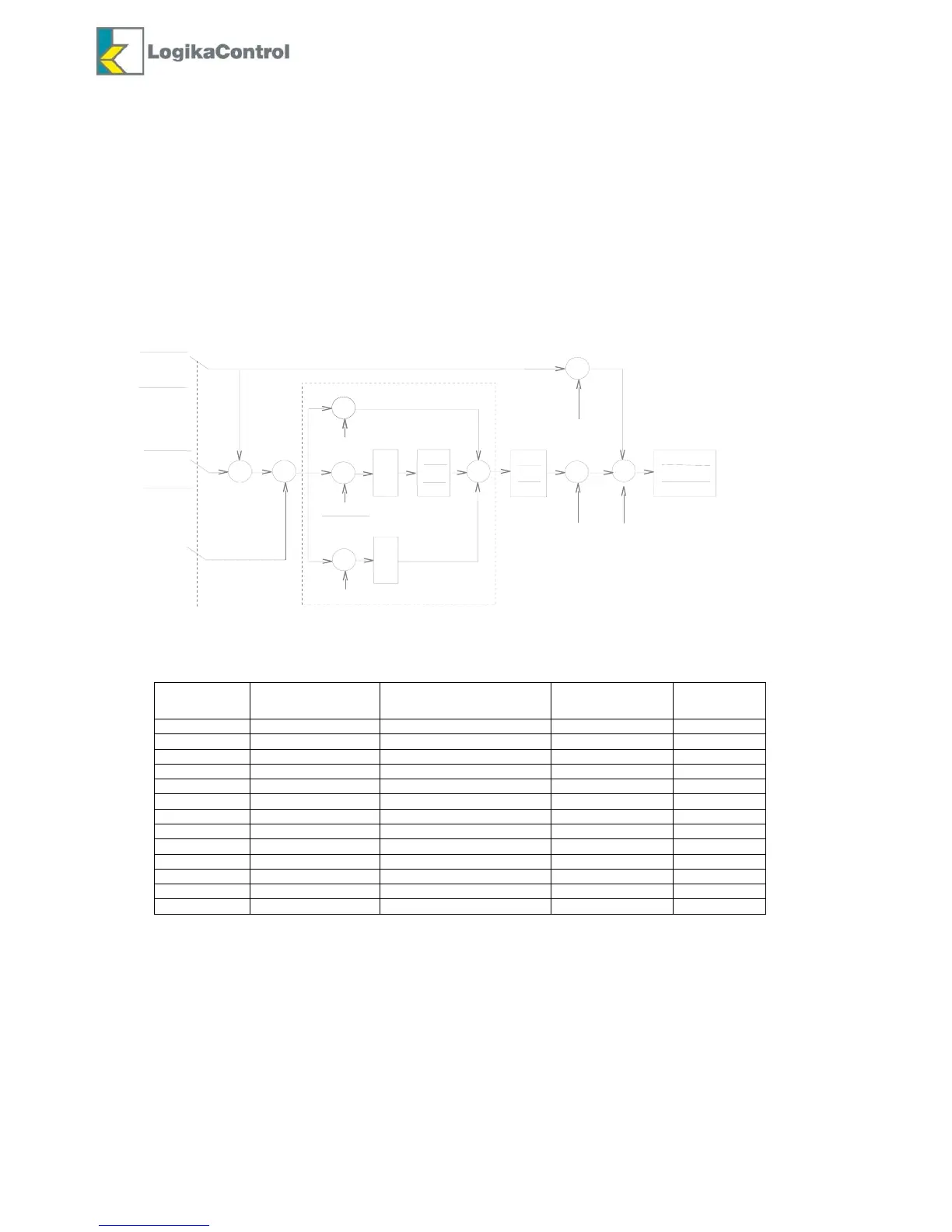
Menu M1-9 allows to visualize/set the parameters related to the PID regulator.
The pic. below shows the PID calculation.
NOTE:
For all the above parameters two default set are provided according the way of control (set on parameter C18).
PID output (limited to the interval 0..1) is transposed to output current: frequency FR1 (PID output=0) correspond 4mA,
frequency FR2 (PID output=1) correspond 20mA.
You have to set the frequency reference on the inverter so that 4mA/20mA input correspond the frequency ranged you
need. You have to set such range both on parameters FR1 and FR2.
PT3 is the duration of the acceleration/deceleration time in case the compressor has to reach the download status; in this
case inverter reaches the minimum frequency FR1 according ramp PT3.
In case of compressor loading the ramps are PT1, while the speed goes up and PT2 while speed goes down.
In case of pressure regulation, PM1 alters the integrating effect of the error on the setpoint; specially integral time PI2 is
multiplied for PM1 when the pressure is over setopint.
Set PI2 or PI3 zero, the related integration or derivative action is disabled.
 Loading...