Revision 1 – 04.12.2015 14/28
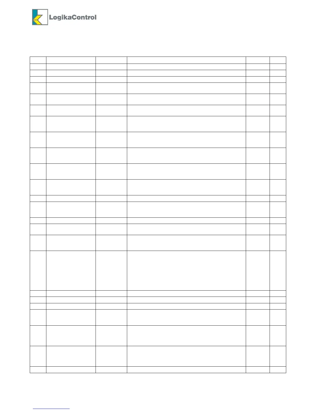
M1-4 COMPRESSOR SETUP
In this menu you can change the general setting of the compressor.
Parameters, setting range, default and password level are reported in the table below:
Restart after power off: MAN (manual) – AUT (automatic)
Starts/hour of the motor allowed
Wt4 operation: YES = fixed – NO = variable
Logika control phases uni:
YES = enabled - NO = disabled
Safety operation:
YES = enabled - NO = disabled
Alarm low voltage :
SI = enabled - NO = disabled
Multiunit options:
0 = stand alone – 1 = Master/Slave
2 = Master/Slave new – 3= Multiunit Slave
Balancing working hours:
in case of setting “00” the balancing is not allowed; Master
is the compressor with address 1
Slave support:
After power on if Master unit has not reached stop set until
the time set in this parameter, the slave starts to support
In case of Multiunit Slave, the compressor works on
standing alone and Multiunit Master is informed this
compressori s out of order
Both inverter modulating in Master/slave operation new
SI = noth inverter modulating
NO = master max speed if both units are running
Enter MODBUS address of the compressor
15
alphanumerical
characters
Serial number of the compressor
Capacity: nominal air flow of the compressor (liters/min.)
Input PTC configuration:
NO = disabled – SI = enabled
Input IN7 configuration:
0 = disabled – 1 = door open
2 = control phases relay – 4= high temperature bearings
Relay RL2 setting:
0=default (star contactor)
1=fan - 2 = condensate drain - 3=compressor status
4=alarm - 5 = motor activated - 6 = load valve on –
7 = lubricating - 8 = off - 9 = activation on power on for
the time Wt5
10 = activation on power on for the time Wt5 and
activation in case of alarm
Compressor stop once the timer “Check compressor” is
over:
NO = disabled – SI = shut-off alarm
Operation output 4/20mA and PID:
0= disabled
1 = enabled on working pressure control
2 = enabled on air end temperature control
Configuration auxiliary input 4/20mA:
0=disabled – 1= relative pressure (delta in relation to the
working pressure) – 2=power inverter – 3=current inverter
4=inverter temperature
Delay timer separator filter alarm
 Loading...