Revision 1 – 04.12.2015 4/28
TECHNICAL FEATURES
- Industrial control equipment for the operation and management of screw compressors only, pollution degree 2.
- In accordance to EC Directives:
- Directive:
- LVD : 2014/35/UE
- EMC: 2014/30/UE
- RHOS: 2011/65/EU
- based on the following harmonized standards applied:
- SAF-EMC: EN 60730-1
- RHOS: EN 50581
- In accordance to UL 508 (FILE #: E316817).
- Black auto-extinguishing box in ABS:
- a) according EC: IP64 for the front panel and IP20 for the other parts;
- b) according UL: type 1 and Type 12 for front panel mounting , installation in pollution degree 2 for the other parts
- Inputs and outputs via terminal-block board to wires (250V, 10A, 12-24AWG) tightening torque 8 Nm.
- Working temperature: 0°C (32°F) ÷ 50°C (122°F) 90% RH (non condensing)
- Storage temperature: -20 (-4°F) ÷ +70 °C (158°F)
- Power supply: 12Vac ± 10% 50 ÷ 60 Hz. (power of the transformer’s secondary: ~ 9 VA) from safety transformer
- Max. current absorbed = ~ 350 mA
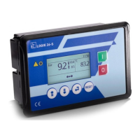
- Visualization through back light alphanumerical LCD 20 digits x 2 rows and nr. 1 led for alarm status
- Messages selectable in 8 languages: Italian – English – French – German – Spanish – Portuguese –
Turkish – Russian
- nr. 6 key buttons: increase, decrease, enter, reset, start, stop
- nr. 1 input for temperature probe KTY13.5/NTC 10KOhm@25°C, ß(25/85)= 3977
- nr. 1 input for pressure transducer (working pressure P1)
- nr. 1 input for auxiliary pressure transducer (internal pressure P2) or analog information from inverter
- nr. 1 input for PTC or Klicson for motor protection (IN8).
- nr. 7 opto isolated digital inputs from 12/24Vac to detect:
IN 1 = emergency stop button
IN 2 = thermal motor
IN 3 = thermal fan
IN 4 = remote start/stop
IN 5 = air filter pressure switch
IN 6 = separator filter differential pressure switch
IN 7 = settable as: door of the electrical cabinet open – control phase relay – generic alarm
- nr. 3 digital inputs for connection to Logika Control phases unit.
- nr. 7 outputs via relay with contact 1.5A AC1 250Vac – 6 A AC1 250Vac total
RL1 = line contactor
RL2 = delta contactor
RL3 = star contactor
RL4 = load solenoid valve
RL5 = fan contactor
RL6 = settable as fan contactor, condensate drain, compressor status
RL7 = settable as: alarm, fan contactor, condensate drain, compressor status
- nr. 1 real time clock with buffer battery, around 10 years electrical life
- nr. 1 24Vdc power supply input for PNP outputs
- nr. 1 24Vdc input from inverter to detect inverter fault
- nr. 2 PNP digital output to control the inverter (run and jog command)
- nr. 1 analog output 4÷20 mA for inverter operation
- nr. 2 serial output RS485 for:
connection to other compressor for Master/Slave and/or Multiunit operation
inverter communication
- Check min. and max. power supply to the controller
- Non volatile memory to store setting data, working hours, compressor status, alarm list
- The controller switches OFF due to micro interruption longer than ~ 300 m.s.
Weight: 470 g
Accessories:
- nr. 1 temperature probe KTY 13.5 for detection of the air end temperature: cable in silicone rubber, length 2.5 m,
working range –10 ÷ 130°C, resolution 1°C.
- nr. 1 pressure transducer 4-20 mA for working pressure control: 2 wires, AISI 316L stainless steel membrane,
working range 0 ÷ 15 bar, resolution 0,1bar, precision ± 0,1bar.
- nr. 1 Logika Control phases unit for power supply 230 ÷ 460V three phase
 Loading...