page 31
Pc-Board MAPRO04
The pc-board MAPRO04 is the main control logic of the MicorMIG machines.
Functions
- welding process control
- weld sequence control
- fan control
- open circuit voltage generator
- temperature monitoring
- monitoring primary input current
- monitoring welding- current/voltage
- communication operating elements (front panel, remote control)
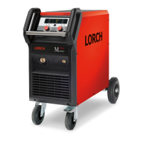
Picture pc-board MAPRO04
X2
X7
X1
X6
X4
X5
X8
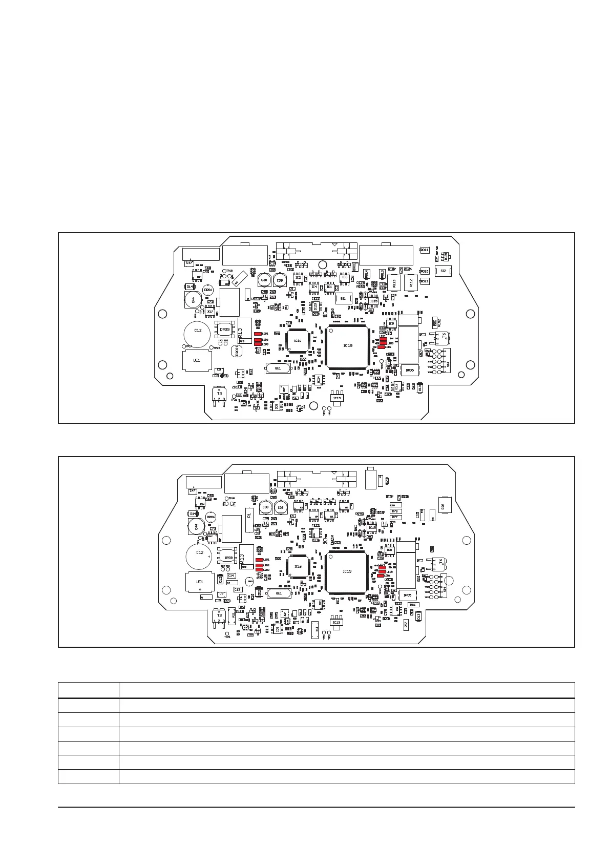
Change MAPRO04 since July 2015
X4
X5
X2
X7
X1
X6
X8
Overview connectors pc-board MAPRO04
connector designation
X1 connector at ribbon cable to pc-board DRV
X2 connector at ribbon cable to dront panel
X5 connector shunt resistor and pc-board DC0x
X6 connector water-sensor (only at version with 2-pin X6 connector)
X7 connector to pc-board DRV
X8 LorchNet
 Loading...