page 32
Pc-Board DMR-RT3
The pc-board DMR-RT3 is the wire feed control of the MicorMIG machines.
Functions
- driving and monitoring the wire feed motor
- monitoring torch trigger switch
- communication PowerMaster torch
LEDs
LED status designation
1 (red) o until software version 1.11: normal operation
from software version 1.12 on : micorprocessor not working
blinking until software version 1.11: malfunction LorchNet (CAN bus)
from software version 1.12 on : normal operation
lit weak micro processor not programmed
on micro processor detected a fault
2 (green) on 5V supply voltage ok
o 5V supply voltage missing
3 (green) on wire retract active
o normal wire feed
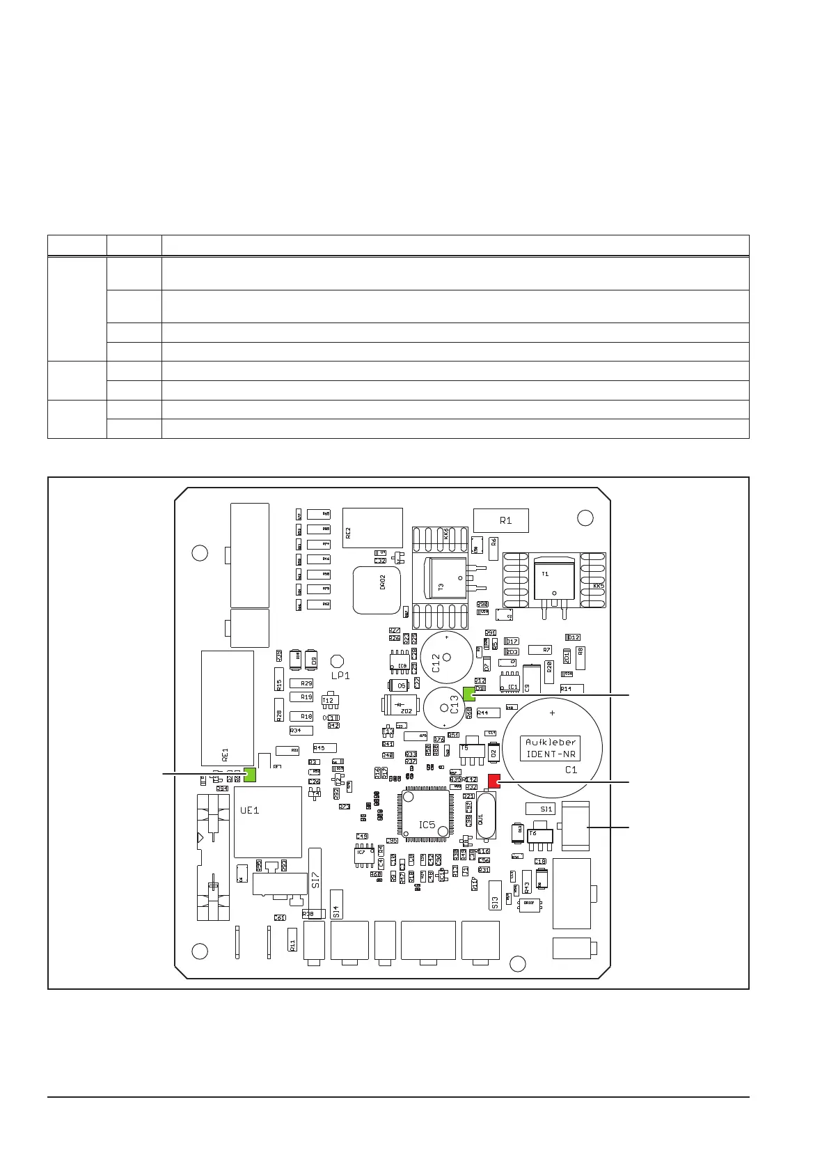
Picture pc-board DMR-RT3
X11 X10
X4 X5 X1
X13
X3
X12
X20 X7
X6
X8
X9
X14
LED2
LED1
LED2
+5V
LED1
error
LED3
retract
X9
LED3
! CAUTION ! the cable-bridge on connector X13 pins 5 and 11 must always be present.