6
v130207
BERNT LORENTZ GmbH & Co. KG Kroegerskoppel 7, 24558 Henstedt-Ulzburg, Germany, Tel. +49 (0) 4193 7548 - 0, Fax - 29, www.lorentz.de
Errors excepted and possible alterations without prior notice.
3 Installing the Solar Array
3.1 Location of the Solar Array
Sunlight is the “fuel” that drives a solar pump. Full solar
exposure of the solar array is critical for full performance
of a solar-direct system. Choose a location for the solar
array that has unrestricted sun exposure throughout the
day all the year. The array can be placed several hundred
feet (100 m) or more from the wellhead. There will be
no loss of performance if the electrical wire is sized
properly, but naturally, the cost of wire will increase
significantly.
The system sizing table specifies wire size require-
ments for both normal and extended wire lengths.
CAUTION Shading a small portion
of a PV array may cause the pump
to stop completely.
Each PV module (panel) contains a series of solar cells
(typically 36 or 72 cells). Every cell that is shaded acts
like a resistor, reducing the output of the ENTIRE
ARRAY. Shading just a few cells will reduce the power
disproportionately, and may stop the pump. Consider
this when deciding where to install the array.
To determine where shadows may be cast at any
time of the year, you can survey the site with a Solar
Pathfinder
®
. This device is especially useful in forested
areas or wherever there are obstructions nearby. It
is available directly from Solar Pathfinder (USA), tel.
++1 (317)501-2529, fax ++1(931)590-5400, www.
solarpathfinder.com
Place the bottom edge of the array at least 2 ft (0.6 m)
above ground to clear rain spatter, growing vegetation
and snow. Keep in mind that trees and perennial plants
will grow taller in the coming years.
3.2 Solar Array Assembly Methods
There are two ways to install the solar array.
1. Assemble the array on the ground, wiring and
all, then lift the entire assembly onto the pole or
roof. A system of 300 W or more may require the
assistance of a backhoe, boom truck or crane to
lift it over the pole.
2. Assemble the array piece-by-piece on the pole. If
the pole is higher than about 6 ft (2 m), it is best
to construct a temporary platform, like a scaffold
assembly commonly used in building construc-
tion. A scaffold system can be rented from a local
supplier.
3.3 Solar Array Mounting Rack
WARNING Your mounting structure
must be engineered for wind
resistance and safety.
Follow the rack (or tracker) manufacturer’s instructions
that are packed with your rack.
Solar tracking A solar tracker is a special pole-moun-
ted solar array rack that tilts automatically to follow the
daily path of the sun. In clear summer weather, it can
increase your daily water yield by 40-50 %. (It is much
less effective in winter and in cloudy weather.)
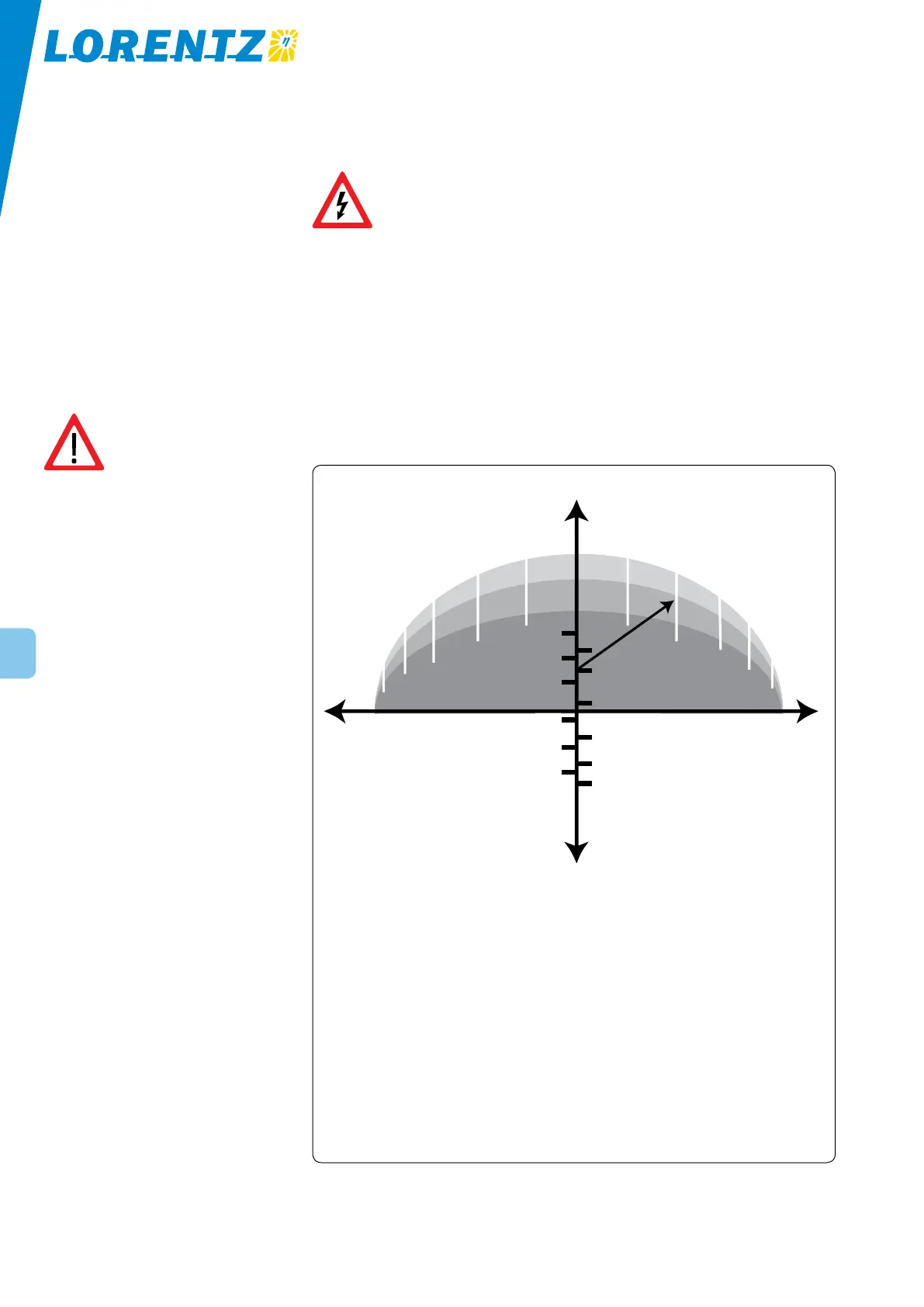
Sun Compass instructions
1. Draw an arrow from month dot to intersec-
tion of your local standard time and latitude
Northern (50°N to 70°N). The gray line is an
example: August, 2pm at 40°N lat.
2. Stand and face your shadow.
3. Hold this page horizontally.
4. Point the arrow that you drew to center of
your shadow.
5. Sun Compass™ now points to the four
directions.
Sun Compass™ is available for the following
latitudes:
1. U.S.A. (25°N to 55°N) – shown here
2. Northern (50°N to 70°N)
3. Equatorial (20°N to 20°S)
4. Southern (10°S to 40°S)
To obtain reproduction rights, contact: John Veltman
PO Box 23533, Santa Fe, NM 87502, USA
North
South
June
July
May
August
April
September
March
October
February
November
January
December
pmam
EastWest
3.4 Orienting the Solar Array to Solar South
For full performance, your solar array must be oriented
within 10° of true (solar) South. Depending on your
location, a compass reading may show an error of as
much as 20°. To correct this discrepancy, apply the mag-
netic declination for your region. Many regional maps
indicate the magnetic declination. If you do not have a
compass but can see your shadow and know the time of
day, use the Sun Compass
™
.
Figure 1: SunCompass
™