16
v130207
BERNT LORENTZ GmbH & Co. KG Kroegerskoppel 7, 24558 Henstedt-Ulzburg, Germany, Tel. +49 (0) 4193 7548 - 0, Fax - 29, www.lorentz.de
Errors excepted and possible alterations without prior notice.
Potential problems with the low-water probe
in surface water The probe has a moving float. It
is highly resistant to deposits and debris. However, it
may stick under some extreme conditions, especially
from algae or water creatures (snails, etc.) that may be
present in surface water.
Possible solutions are:
1. Hang the probe independently of the pump and
pipe (clamped to a weight, but not to the drop
pipe). This way, it can be pulled up for inspection
or cleaning without the need to pull the pump.
(This may not be feasible if the well casing is
smaller than 6 in.)
2. Pull the probe out periodically (with the pump if
necessary) for testing and inspection. The pump
should stop at the moment the probe leaves the
water.
3. Wrap the probe in a protective screen (fiberglass
window screen, for example). Substitute a differ-
ent type of float switch. You can use any switch
that makes contact on rise (normally open).
WARNING Running completely dry
will damage the pump and void
the warranty. The purpose of the
probe system is to sense the loss
of water and turn the pump off
before it can run dry.
CAUTION The low-water probe
must be positioned vertically,
within 10°. If the pump is NOT to
be installed vertically, find an
alternative way to mount or suspend the probe,
so that it is higher than the pump, and in a
vertical position.
CAUTION Do not use a pressure
switch with a “low water cutout”
or “loss of prime” feature as a
method of dry-run protection. A
helical rotor pump will maintain pressure as it
runs dry, so this method will not work reliably.
For pressure switch information, see section
4.13, Pressurizing Systems
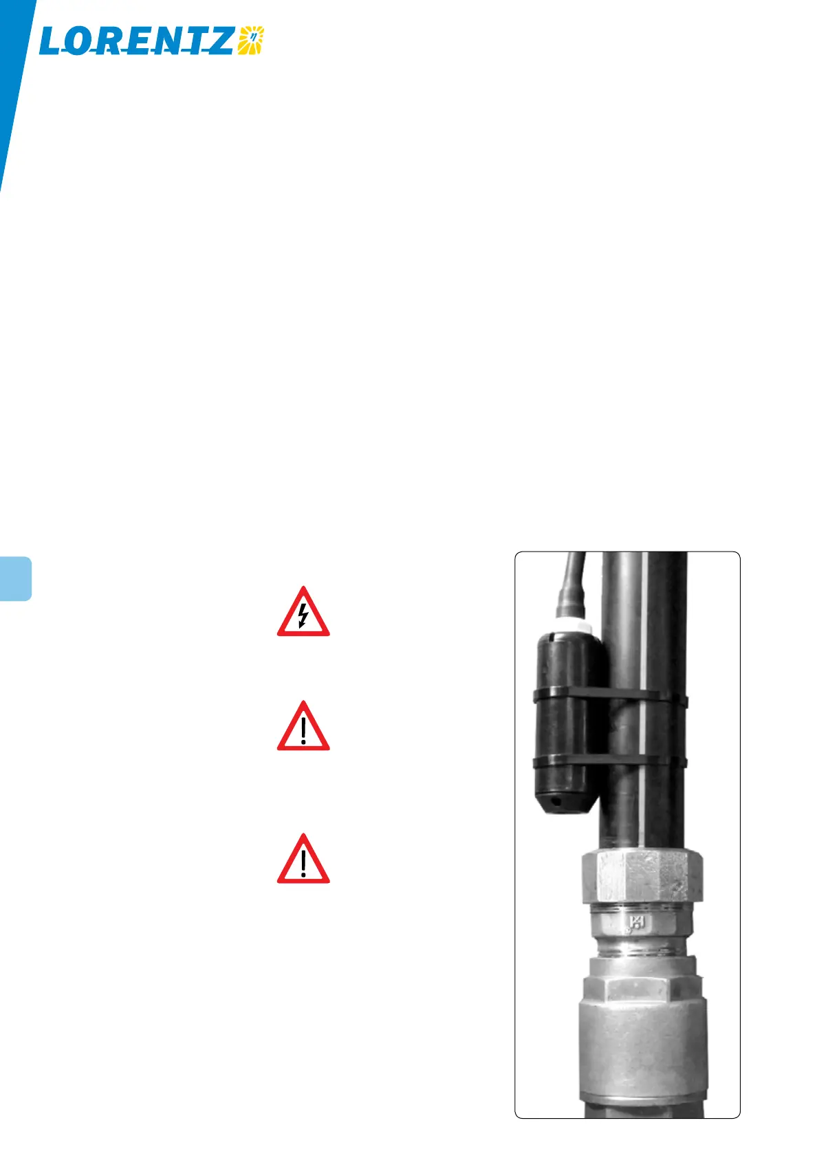
Figure 13: Low-water probe installed in the
standard position, for a pump that is positioned
vertically
4.10 Low-Water Probe for Dry-Run Protection
Installation The probe is packed with two stainless
steel hose clamps. For a pump that is to be installed in
a vertical position, clamp it to the pipe just above the
pump outlet, as shown in the photo. Splice the two
probe wires using the splice kit components that are
packed with the probe. The assembly procedure is the
same as the main pump splice.
If you are NOT using the well probe, it must be
bypassed. Connect a short wire between the probe
terminals in the junction box (terminals 1 and 2). Do this
only if you feel certain about the reliability of the water
source. Wire size: #18 AWG (1 mm
2
) or larger.
Principle of operation The probe contains a me-
chanical float with a magnet inside. When the probe is
submerged, the float rises, and the magnet actuates a
switch. The switch closes (makes contact) to indicate the
presence of water. The switch is sealed, so the contacts
never touch the water.
If the water level drops below the probe, the float drops,
and the switch opens (breaks contact). The controller
will stop the pump and the “Low-Water OFF” light
will indicate. When the water level recovers and switch
closes again, the controller will delay the restart for 20
minutes. This gives time for the water level to recover.
To force a quick restart, turn the controller off, then on
again.
NOTE Pumps made before October 2003 may
have a different type of probe, with wet
electrodes. Either type can be used with the PS
series controllers.
The Low Water-OFF light flashes slowly for the
remainder of the day, even if the water recovers and
the pump restarts automatically. This tells you that the
water source ran low at least once since the power was
disrupted (or sun went down). To turn the light off, reset
the controller by turning it off/on.