14
v130207
BERNT LORENTZ GmbH & Co. KG Kroegerskoppel 7, 24558 Henstedt-Ulzburg, Germany, Tel. +49 (0) 4193 7548 - 0, Fax - 29, www.lorentz.de
Errors excepted and possible alterations without prior notice.
4.6 Maximum RPM Setting
All PS controller offer the option of reducing the maxi-
mum speed of the pump.
This RPM control reduces the maximum speed (RPM
limit) to as low as about 30 %. It will NOT reduce the
starting or low-light performance. The pump uses less
power when it pumps less water.
Reasons to reduce the maximum RPM:
1. To prevent over-pumping a limited water source.
See section 5.8, Utilizing a Low-Production Water
Source
2. To improve energy and water-source manage-
ment in a battery system where slow pumping is
adequate to meet the demand
3. To limit the back-pressure (and prevent possible
pump overload) when pumping into a direct-
pumped irrigation system, a filtration system, or
an undersized pipeline.
How to reset the Maximum RPM setting:
1. Remove the bottom end of the PS controller
enclosure (the end with the conduit openings)
2. Locate the adjustment knob shown in the photo
below (circled)
3. In most cases, the knob will be at the standard
factory setting full clockwise as indicated by
“setting #1” illustrated below. Turn it counter-
clockwise to the desired setting. The exact posi-
tions may vary from this illustration. Follow the ink
marks on the controller.
CAUTION If you perform this
adjustment, record the setting on
the System Report Form, see
section 13. If flow testing is done
in the future, the result may lead to a wrong
conclusion if this adjustment is not accounted
for.
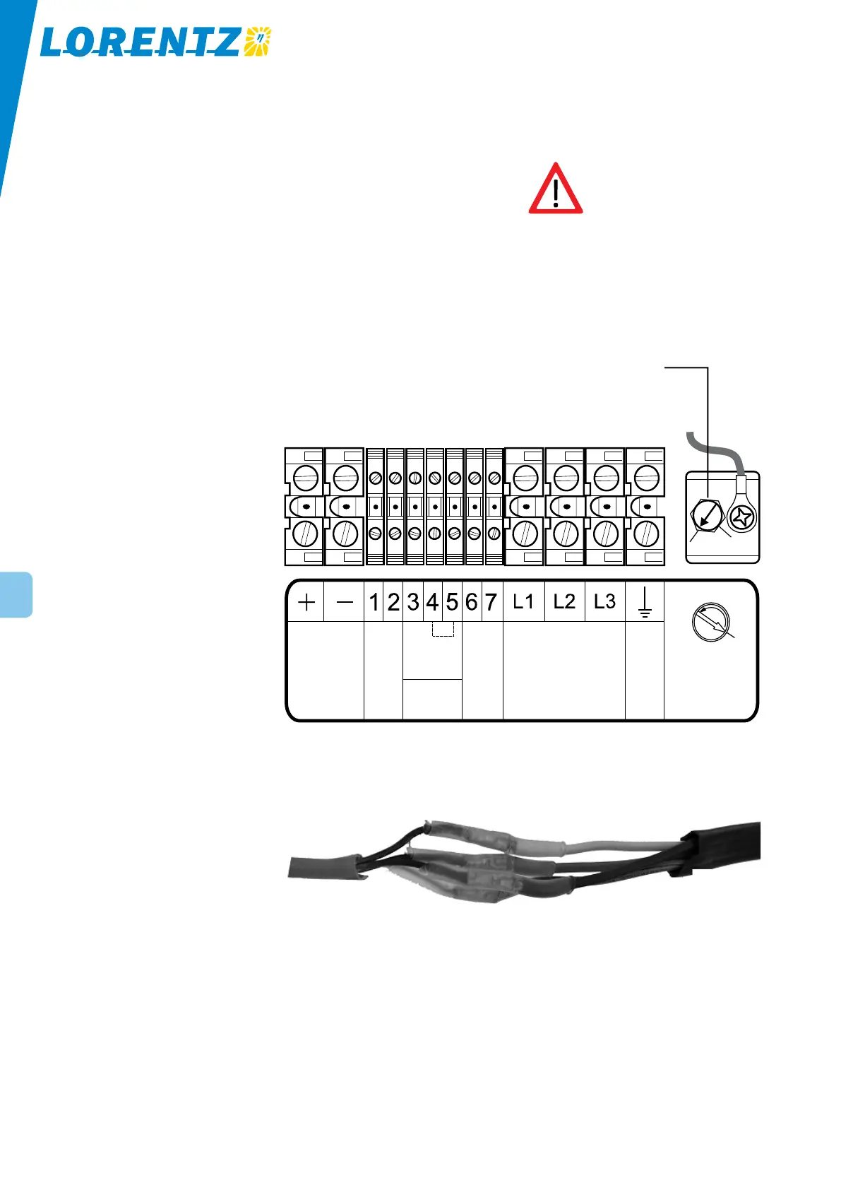
Power In
Pump
Max. RPM
Setting
Low-water sensor probe
connect to bypass
For factory
testing only
To reverse direction,
reverse any two wires
Factory setting:
Maximum
GROUND
Remote
Float
Switch
NO
COM
NC
Figure 11: Terminals inside the PS controller
Maximum RPM
Setting Knob
4.7 Submersible Pump Cable and Splice
Selection of cable Use only an approved type of
submersible well pump cable, the same type that is used
for conventional AC pumps. It is available from your
pump supplier or installer, or a local water well supply
distributor. You need 4-conductor cable. It is often called
“3-wire-with-ground” because it has 3 power wires plus
a ground wire. To determine the minimum required wire
size, refer to the Systems Sizing Table.
Submersible Splice A splice kit includes crimp connectors
to join the copper wires, adhesive heat-shrink tubing,
and instructions. If the drop cable is too large to fit in
the crimp connector, cut off some of the wire strands.
Use a crimping tool, and observe that the wires are held
very securely.
motor leader cable
wires spliced with
adhesive heat-shrink tubing
drop cable
Figure 12: Cable splice