8
v130207
BERNT LORENTZ GmbH & Co. KG Kroegerskoppel 7, 24558 Henstedt-Ulzburg, Germany, Tel. +49 (0) 4193 7548 - 0, Fax - 29, www.lorentz.de
Errors excepted and possible alterations without prior notice.
cleanliness and safety. Place the controller near the
batteries but NOT in the same enclosure. They must
be safely isolated from the battery terminals and from
corrosive gasses.
WARNING To be installed,
connected and serviced by
qualified personnel only. Ensure all
power sources are disconnected
when making connections to the
controller. Follow all appropriate
electrical codes. There are no user
serviceable parts inside the motor
or the controller.
CAUTION Loose connections are
the most common cause of system
failures. Pull on each connection to
confirm that it is secure.
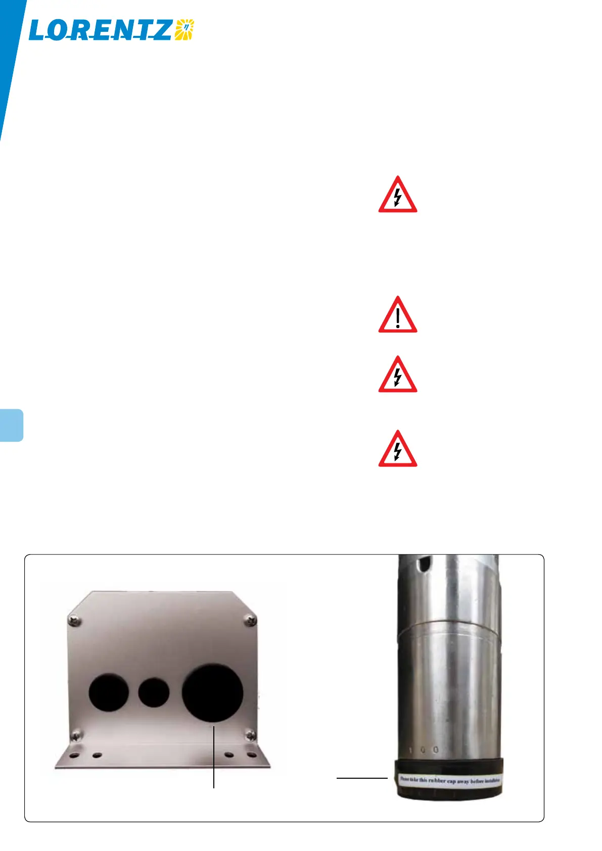
WARNING The black rubber caps
on the Controller cover are only
transportation covers and must be
replaced buy code compliant
conduit fittings.
WARNING Submersible motors are
delivered with a rubber boot on
the bottom oft he motor. This is
only a transportation measure and
must be taken off before
installation.
4 Electrical Installation
4.1 Controller, Junction Box and Conduit
Protection caps and boots Before installation,
remove all protection caps from the junction box and
replace them with code-compliant conduit fittings.
Likewise, remove the protection boot from the bottom of
submersible motors.
Location Place the controller close to the solar array,
not the pump. This will reduce the risk of lightning dam-
age. The controller’s input circuitry is more sensitive to
surges than its output. It is safest to minimize the length
of the input wiring.
Protection from solar heat Electronic devices are
most reliable when they are protected from heat. Mount
the controller in the shade of the mid-day sun. An ideal
location is directly under the solar array, on the north
side of the mounting pole. If shade is not available, cut
a piece of sheet metal and bolt it behind the top of the
controller. Bend it over the controller to provide shade.
This is especially important in extremely hot locations.
Extreme heat may trigger a thermal switch in the
controller and cause it to turn off.
Location of controller Mount the controller vertically
to keep out rainwater. It is preferable to mount it ON
THE NORTH SIDE of a pole or other structure, to help
reduce solar heating. This may also allow easiest access
without hitting your head on the lower (South) edge of
the array.
Junction box (optional) A pre-wired junction box is
available for your system. The junction box terminals
will handle pump wires as large as AWG #6 (13 mm
2
). If
large wires cannot be accommodated easily in the box,
you can join them to smaller wires in the junction box.
AWG #12 (4 mm
2
) or larger is acceptable for this very
short length. Do NOT remove terminal screws. If the key
to the junction box gets lost, it can be opened with a
screwdriver.
Mounting the controller and junction box to a
pole The controller can be mounted onto the solar array
support pole using materials available from your local
electric supply store. The best mounting hardware is
“slotted strut” (Unistrut
®
or equivalent) with matching
conduit clamps to fit around the mounting pole. This
makes a very strong assembly that is easy to adjust. In
North America, these materials are commonly available
from electric suppliers.
Electrical conduit is recommended We urge you to
use electrical conduit (pipe) to protect outdoor wiring
from the weather, from human activities, and from
chewing animals. If you do not use conduit, use strong,
high-quality outdoor cable. Where cables enter the junc-
tion box, install sealed strain-relief cable clamps.
Keep the controller and junction box sealed Un-
used holes must be sealed to keep out animals, insects,
water and dirt. Each hole is supplied with a rubber plug
that can be kept in place for this purpose.
Battery system Batteries must be in a cool location
for best longevity, and in a protective enclosure for
Figure 2: Transportation protection caps and boots
rubber caps
rubber boot