20
v130207
BERNT LORENTZ GmbH & Co. KG Kroegerskoppel 7, 24558 Henstedt-Ulzburg, Germany, Tel. +49 (0) 4193 7548 - 0, Fax - 29, www.lorentz.de
Errors excepted and possible alterations without prior notice.
4.13 Pressurizing Systems
LORENTZ PS pump systems are excellent for
automatic water pressurizing when powered by
a battery system. If you are raising water vertically
AND pressurizing, the pump must handle to total head.
Note the relationship: 2.31 ft = 1 PSI (1 bar = 10 m verti-
cal) Example: A pump that lifts 100 ft (30m) vertical and
pressurizes to 60 PSI (4 bar) must pump the equivalent
of 240 ft (70 m). Be sure your pump was chosen correctly
for your application. The installation is similar to that of
a conventional AC pump.
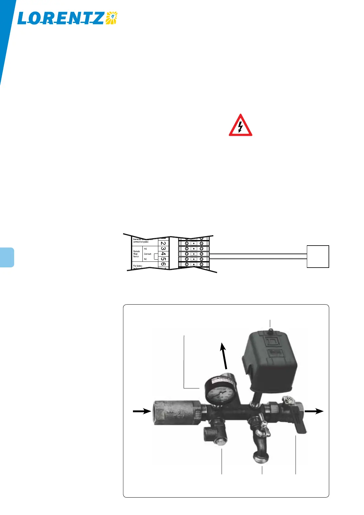
A typical pressurizing control assembly is il-
lustrated in the following photo. These are standard
components, same as used for conventional AC water
pressure systems. The parts (from left to right) are:
1. check valve (prevents back-flow)
2. pressure gauge 0-100 PSI (0-7 bar)
3. pressure relief valve 75
PSI (5.3 bar)
4. tank tee (a bronze casting that holds all the
components)
5. pressure switch (turns the pump on/off according
to pressure set-points, adjustable)
6. hose outlet (to drain the system or to supply water
when outlet is shut off)
7. ball valve (to shut off the supply to the outlets)
The components can be purchased from local suppliers,
or as a kit from your pump supplier.
Pressure tank A pressure tank is required. We recom-
mend a captive-air pressure tank of 40 US Gal. (150 l)
OR MORE, to assure a steady supply of water pressure
as the pump cycles on and off and the water demand
varies. A large tank is always best. Size and cost are the
only practical limitations. More than one tank can be
used to increase the total capacity.
How to pre-charge a captive-air pressure tank
for PS pump systems For the system to function
properly, the air bladder in the tank must be pre-charged
with air according to these instructions.
1. Make note of the cut-in setting of the pressure
switch (either by observation or knowing the
factory setting).
2. Turn off the pump and exhaust the water from the
tank if necessary, so the water pressure is 0.
3. Find the air fitting on top of the tank. Measure the
air pressure in the tank using a tire gauge.
4. Adjust the pressure to about 3 PSI (0.2 bar) LESS
THAN THE CUT-IN PRESSURE.
Pressure switch PS pumps systems can use an ordinary
pressure switch sold for conventional AC pumps. Do not
use a pressure switch with “low water cutout” or “loss
of prime” feature (with a shutoff lever on the side). It is
intended to prevent dry run of centrifugal pumps. The
helical rotor pump types will maintain pressure even
as it runs dry, so this device will not work reliably. It
will also shutoff if the pressure falls due to high water
demand.
Pressure switch connection There are two ways to
connect the pressure switch:
1. primary power switching The switch is used to
disconnect the DC power source. Wire the switch
between the power source distribution point and
the controller, as you would with a conventional
pump.
2. remote switching This method uses the
“remote float switch” terminals. Small wire (mini-
mum #18 AWG / 1 mm
2
) can be run to the pres-
sure switch from a long distance. See illustration
below. Advantage: the controller stays on all the
time. If the water source runs low (even if it recov-
ers) the “Source Low” indicator light will stay on
to notify the user. Power draw of the controller in
OFF mode is only about 1 watt.
WARNING A PRESSURE RELIEF
VALVE IS REQUIRED. If the pressure
switch fails, this will prevent
extreme pressure from bursting
the tank or piping and causing a flood. Install
the valve near the pressure tank, before the
shutoff valve. Use a 1/2 in (or larger) valve set
about 25 – 75 % higher than the cut-out pressure.
Run a pipe or hose from its outlet to a drain or
to the outdoors where water discharge will not
cause damage.
Figure 17: Wiring for pressure switch
pressure switch
pressure gauge to pressure
tank
WATER IN
from pump
WATER OUT
to distribution
system
check valve hose outlet tank tee
Figure 18: Typical assembly for automatic water pressurising