Page 6
Lotus Service Notes Section HI
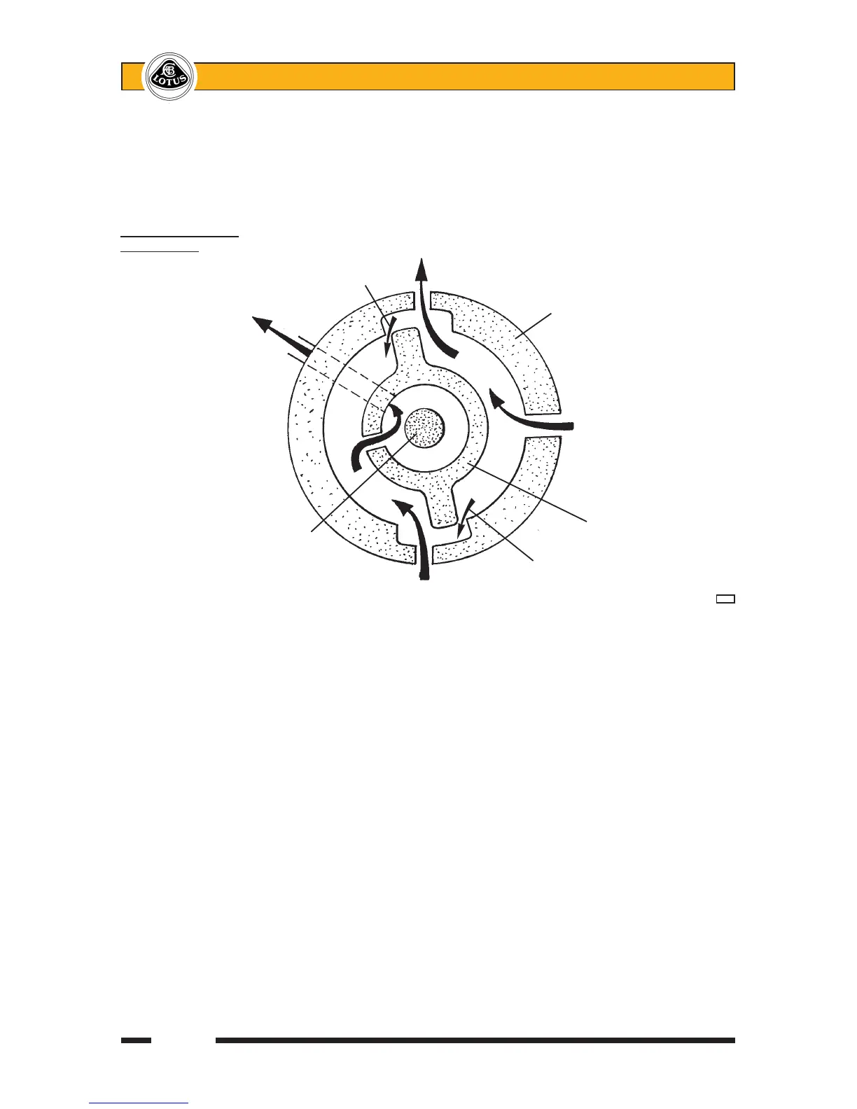
The schematic diagram below shows the principle of valve control, although in practice, six pockets are
machined in the rotor and sleeve, and the valve system is repeated three times. The valve sleeve is provided
with four sealing rings in order to divide the inlet and outlet feeds and connect with ports in the valve body,
whilst allowing 360°rotation of the valve assembly.
The engine driven pump supplies oil at a controlled rate. A progressive restriction of this oil flow will cause
the pressure to increase whilst the flow rate is maintained. Eventually, when the flow is completely restricted,
the pressure will rise to the relief valve setting in the pump, causing oil to flow through the relief valve and re-
circulate within the pump.
The hydraulic valve in the steering gear provides this restriction according to the force applied at the
steering wheel and the loading on the front tyres. The valve is configured as 'open centre' such that when no
torque is applied to the steering wheel, there is minimal restriction to the oil supply, resulting in low oil pressure
and the freedom to flow to both rack cylinders and through the outlet port back to the reservoir. The pressure
differential across the rack piston is zero.
When the steering is turned to the left against some resistance, the input shaft/rotor transmits the motion
to the pinion gear/valve sleeve via the torsion bar, which twists in proportion to the effort applied at the wheel
and the resistance at the tyres. Effort is high typically at slow vehicle speeds, or when parking. When the bar
twists, the angular position of the rotor relative to the valve sleeve alters, with the result that the ports to cylin-
der 1 become biased towards the pressurised supply, and the ports to cylinder 2 biased to the reservoir return
port at low pressure. Hence a pressure differential is created within the rack housing, with higher pressure in
cylinder 1 applying a force to the steering rack piston to assist the turn.
If the steering is turned hard against resistance, or the lock stop, the valve will completely close off the
return path and cause delivery pressure from the pump to rise until the pressure relief valve in the pump opens;
maximum assistance has been reached.
The ultimate degree to which the torsion bar is permitted to twist, is limited by mechanical contact between
the input shaft and the pinion gear. This mechanism prevents the torsion bar being over stressed, defines the
maximum level of assistance, and provides a safety back up in case of torsion bar failure; steering control would
be retained, albeit with a small amount of lost motion.
RHD steering being Pressurised oil to
turned to left Restricted return RH rack cylinder
pathcausessupply Valvesleeve-xedtopinion
side pressure increase Angular position to rotor
displacedduetoexin
Return to torsion bar
reservoir
Oil supply
from pump
Valve rotor/input shaft
Torsionbar(connects (xedtocolumn)
valvesleevetorotor)
Restricted return path
causes supply side
Oil returning from pressure increase h40a
LH rack cylinder