Page 4
Lotus Service Notes Section DJ
Alignment
Wheel alignment refers to the parallelism of the wheels when viewed from above and is crucial to vehicle
stability, handling and tyre wear. It is measured either by the angle a wheel makes with the vehicle centre
line, or the difference in dimension between the wheel rim to wheel rim measurement at the front and rear of
the wheel at hub centre height. The wheels are said to 'toe-in' when the wheel paths converge ahead of the
vehicle, and 'toe-out' when they diverge. Rear wheel alignment should be measured only using equipment
which measures individual rear wheel alignment relative to the car centreline. Wheel alignment is designed
to vary with suspension travel ('bump steer') and the base setting should be measured only at the specified
mid laden ride height.
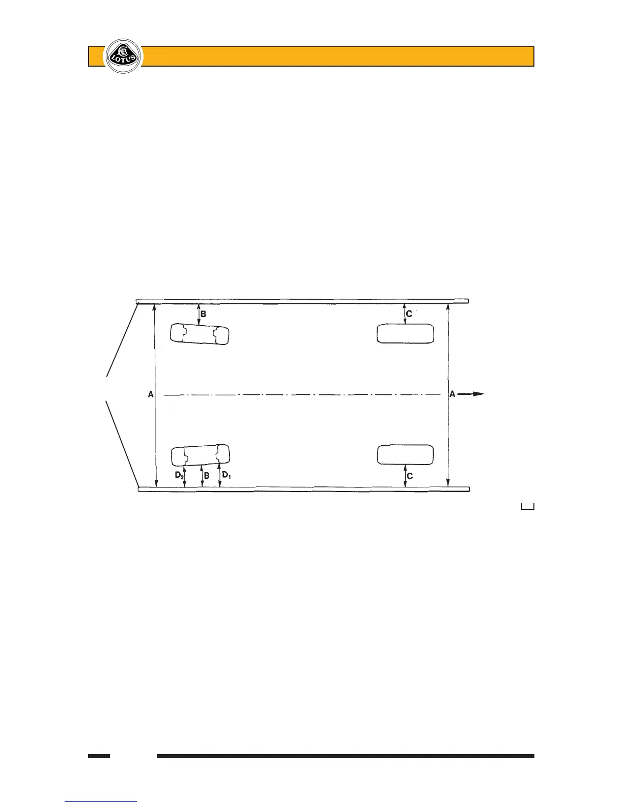
It is possible to accurately measure individual wheel alignment using a pair of long straight bars or round
section elastic in conjunction with 4 axle stands or similar. Any bars used must be longer than the length of the
car, and be suitably stiff and straight.
Set up the bars or elastic on each side of the car at wheel centre height as shown an the diagram, so that
A = A, B = B and C = C.
Measure the distance from the bar to the rim of the wheel concerned at the front and rear of the centre line
of the wheel (D1, D2). If the front dimension, D1, is greater than the rear dimension, D2, the wheel has TOE-IN.
If the rear dimension is greater than the front dimension, the wheel has TOE-OUT. The difference between the
two measurements is the amount the wheel has toe-in or toe-out.
Wheel alignment is adjusted via the toe control link which is equipped with a turnbuckle at its centre.
Slacken both locknuts, and turn the buckle as necessary to increase or decrease the effective length of the
link. As a guide, lengthening the link rod by a turn of one 'flat' (one sixth of a turn) will increase toe-in by ap-
proximately 1.6 mm.
After adjustment, hold each section of the toe-link in turn using the flats provided, whilst tightening each
of the two locknuts to 45 Nm. Ensure that the axes of the toe-link pivot bearings are parallel.
Straight
edge FRONT
d21