I422 GB I 10 17 31100212
G
B
13
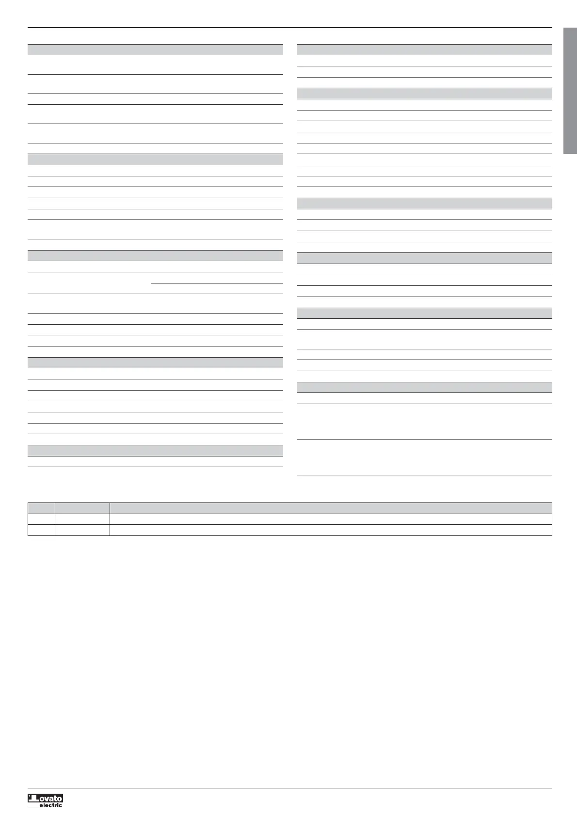
TECHNICAL CHARACTERISTICS
Supply
Rated voltage Us 100 - 240V
110 - 250V=
Operating voltage range 90 - 264V
93.5 - 300V=
Frequency 45 - 66Hz
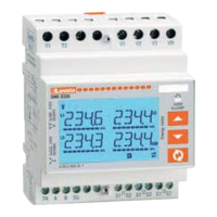
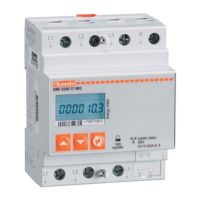
Power consumption/dissipation DMG100 0.5W – 1.5VA
DMG110 0.8W – 2.2VA
Immunity time for microbreakings DMG100 >= 40ms
DMG110 >= 30ms
Recommended fuses F1A (fast)
Voltage input
Max. rated voltage Ue 600 VAC L-L (346 VAC L-N)
Measuring range 90…720 V L-L (50...415 VAC L-N)
Frequency range 45…65 Hz
Measurement type True root mean square (TRMS)
Measurement input impedance L-N - L-L > 8MΩ
Connection method Single-phase, two-phase, three-phase with or
without neutral or balanced three-phase system
Recommended fuses F1A (fast)
Current inputs
Rated current Ie 1 A
or 5 A
Measuring range For 5 A scale: 0.025 - 6 A
For 1 A scale: 0.025 – 1.2 A
Input type Shunt supplied by an external current transformer
(low voltage). 5 A max.
Measurement type Root mean square (RMS)
Overload capacity +20% Ie
Overload peak 50 A for 1 second
Burden (per phase) ≤0.6 VA
Measurement accuracy
Measuring conditions
Temperature +23 °C ±2 °C
Voltage (phase to neutral) ± 0.5% (50…415 V
) ±0.5 digit
Voltage (phase to phase) ± 0.5% (90…720 V
) ±0.5 digit
Current (CT /5) ± 0.5% (0.1…1.2In) ±0.5 digit
Active energy Class 1 (IEC/EN 62053-21)
Reactive energy Class 2 (IEC/EN 62053-23)
Additional errors
Temperature 0.05%/°K per V, A, W
Insulation
Rated insulation voltage Ui 600 V
Rated impulse withstand voltage Uimp 9.5 kV
Power frequency withstand voltage 5.2 kV
Ambient conditions
Operating temperature -20 - +60°C
Storage temperature -30 - +80°C
Relative humidity <80% (IEC/EN 60068-2-78)
Maximum pollution degree 2
Overvoltage category 3
Measurement category III
Climatic sequence Z/ABDM (IEC/EN 60068-2-61)
Shock resistance 15g (IEC/EN 60068-2-27)
Vibration resistance 0.7g (IEC/EN 60068-2-6)
Auxiliary supply and voltage input connections
Type of terminal Screw (fixed)
Number of terminals 4 for voltage inputs / 2 for Aux supply
Conductor cross section (min… max) 0.2 - 4.0 mm
2
(24 - 12 AWG)
Tightening torque 0.8Nm (7lbin)
Current Input and RS485 (DMG110 only) connections
Terminal type Screw (fixed)
Number of terminals 6 for CT connection / 4 for RS485 connection
Conductor cross section (min… max) 0.2 – 2.5 mmq (24 - 12 AWG)
Tightening torque 0.44 Nm (4 lbin)
Housing
Version 4 modules (DIN 43880)
Mounting 35mm DIN rail (EN60715) or by screw using
extractible clips
Material Polyamide RAL7035
Degree of protection IP40 on front / IP20 terminals
Weight 300g
Certifications and compliance
Certifications obtained cULus, RCM, EAC
Comply with standards IEC/EN 61010-1, IEC/EN 61010-2-030,
IEC/EN 61000-6-2, IEC/ EN 61000-6-3,
UL 61010-1, CSA C22.2 n° 61010-1,
UL 61010-2-030, CSA 22.2 n° 61010-2-030
UL Marking Use 75°C min copper (CU) conductor only
AWG Range: 18 - 12 AWG stranded or solid
Field Wiring Terminals Tightening Torque: 4.5lb.in
Flat panel mounting on a Type 1 enclosure
Auxiliary supply from a system with a phase-neutral voltage ≤300V
MANUAL REVISION HISTORY
REV. DATE NOTES
00 26/01/2015 First release
01 19/03/2015 Change of range for P08.n.05 and P08.n.08
 Loading...