I422 GB I 10 17 31100212
G
B
7
– Press to access the selected menu.
– At this point the sub-menu (if applicable) and sequential parameter number can be selected, again using the buttons as follows:
Back Increase/decrease Next
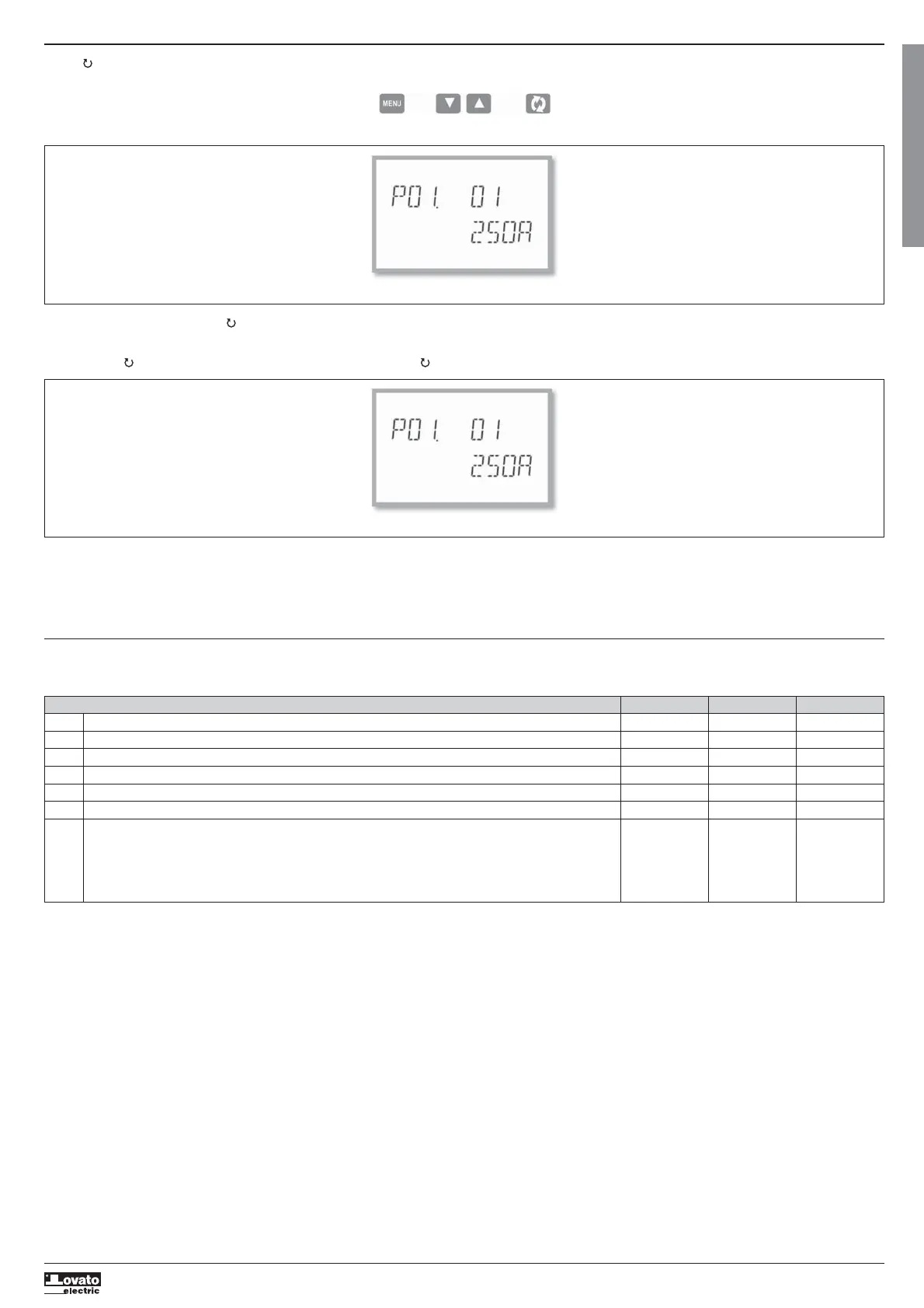
– Once the desired parameter number is set, switches to parameter value edit mode, with the parameter shown in the alphanumeric display.
– Pressing
or
changes the parameter within the permitted range.
– Pressing
and
simultaneously restores the factory default value.
– Pressing
and simultaneously sets the minimum possible value, while pressing
and sets the maximum.
Set-up: selecting the parameter number
– Pressing MENU stores the parameter and returns to the previous level, i.e. parameter selection.
– Press MENU several times to exit and save the parameters. The device will reboot.
– Alternatively, from within programming, holding down MENU continuously for three seconds saves changes and exits directly.
– If no buttons are pressed for two minutes, the set-up menu is abandoned automatically and the system returns to the standard display without saving the parameters.
– Remember that, solely for the data that can be edited using the buttons, a backup copy can be made in the DMG100-110’s EEPROM. If required, this data can be restored to the working memory. The backup and
date restore commands are in the commands menu.
PARAMETER TABLE
– All available programming parameters are indicated in the following table. For each parameter the range of possible settings and factory default are shown, in addition to an explanation of the parameter’s function.
The description of the parameter visible on the display may in some cases vary from that indicated in the table due to the limited number of characters available. The parameter code is a valid reference in any case.
Setting the parameter value
M01 - GENERAL UdM Default Range
P01.01 CT primary A 5 1-10000
P01.02 CT secondary A 5 1-5
P01.03 Rated voltage V 400 50-500000
P01.04 Use VT OFF OFF-ON
P01.05 VT primary V 100 50-500000
P01.06 VT secondary V 100 50-500
P01.07 Wiring configuration L1-L2-L3-N L1-L2-L3-N
L1-L2-L3
L1-L2-L3-N BIL
L1-L2-L3 BIL
L1-N-L2
L1-N
P01.01 – Rated current of CT primary winding.
P01.02 – Current of CT secondary winding.
P01.03 – Rated voltage of system.
P01.04 – Program as ON if VTs are used. If programmed as OFF, the next two parameters are ignored.
P01.05 – Rated voltage of VT primary winding.
P01.06 – Rated voltage of VT secondary winding.
P01.07 – Set in accordance with the connection scheme adopted. See Connection Schemes at the end of the manual.
 Loading...