Do you have a question about the LS ELECTRIC LSLV-G100 Series and is the answer not in the manual?
Explains the classification of safety precautions into 'WARNING' and 'CAUTION' with their meanings.
Explains symbols used for danger and electric shock warnings to ensure user safety.
Details specific cautions for handling the module, like static charge and connection, to prevent damage.
Explains the purpose and benefits of the PROFIBUS-DP communication module for connecting inverters to PROFIBUS networks.
Lists the components included in the product package for the PROFIBUS-DP communication module.
Details the technical specifications of the PROFIBUS-DP communication module, including device type, baud rates, and connector type.
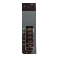
Provides a visual layout of the PROFIBUS-DP communication module, highlighting key components and indicators.
Details the pin assignments and signal descriptions for the PROFIBUS connector on the module.
Provides step-by-step instructions for installing the PROFIBUS-DP communication module onto the G100 inverter.
Explains the procedure for grounding the PROFIBUS-DP communication module using a ground cable.
Details the specifications of the network cable, including AWG, type, insulation, and shield.
Outlines maximum network cable lengths allowed for different baud rates to ensure reliable communication.
Describes the three LED indicators (CPU, ERROR, NODE) on the communication module and their basic functions.
Details how to diagnose device status based on LED signals, including possible causes and resolutions.
Provides a comprehensive list of PROFIBUS-DP communication parameters, including code, name, default, range, and description.
Explains various parameters related to PROFIBUS-DP communication configuration, including version, ID, and LEDs.
Guides on setting the unique Station ID for the PROFIBUS-DP module and the necessary update procedure.
Explains how the status of LED indicators (NODE, ERROR, CPU) is displayed and interpreted on the keypad.
Describes how to configure the number of 'Para Status' data points to be sent to the master device.
Details how to set the 'Para Status' parameters using inverter addresses and group numbers for status information.
Explains how to configure the number of 'Para Control' data points for master device control functions.
Details how to set the 'Para Control' parameters using inverter addresses and group numbers for control functions.
Describes the 'Comm Update' parameter and its role in applying parameter changes to the PROFIBUS-DP module.
Explains how to configure bit swapping for LSB/MSB in network data transmission for compatibility.
Provides fields to fill in for warranty registration and product details for service claims.
Outlines the warranty period and general procedures for obtaining service and support.
Details how to contact authorized LS distributors or service centers for in-warranty issues.
Lists specific cases where the warranty is not applicable, such as misuse or natural disasters.
| Brand | LS ELECTRIC |
|---|---|
| Model | LSLV-G100 Series |
| Category | Control Unit |
| Language | English |