Chapter 2 System Configuration
Sensor that detects human movement
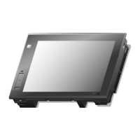
1) Analog Touch Panel: Input by user’s touch
2) LCD: Screen indication
Indicating the state of device (On: Green)
1) Logging/Recipe/Screen Data Backup
2) Send project data and XP-Run time
3) Receive back data and project file
Composed of three ports (Front side 1 port, Lower end 2 ports)
1) USB Memory Connection: Backup of data such as alarm/logging/recipe
and storage of screen data
2) USB Memory Connection: Send/Receive project data, Send XP-Runtime
3) User’s Interface Connection: Using mouse/keyboard
4) Printer connection: Printing function
Fixing XGT Panel on the panel using bracket
Prevention from electric shock
4 channels Video Input Optional board to be developed later
RS-422/485 Terminating
Resistance Switch
RS-422/485 Terminating Resistance On/Off See Communication Instruction
Manual 2.5.1 Switch
Communication, I/O Option Module 3 Units Mounted Optional board to
be developed later
SD Card Safety Removal Switch
1) Backup of data such as alarm/logging/recipe and storage of screen
data
2) Send/Receive project data, Send XP-Runtime
3) Window CE OS Update Function (Can be used with DIP S/W set)
RS-422/485: PLC or Control Device Communication
RS-232C: PLC or Control Device Communication
Ethernet: 10Base-T / 100Base-TX
1) Send Project Data
2) Receive backup data and project file
3) Send XP-Runtime
4) PLC/Control Device Communication
Composed of Power Input and FG Terminal
(1) For further details on connection of communication, please refer to Communication Instruction Manual.
(2) For further details on installation, please refer to the Chapter 10.
 Loading...