1. Basic System Configuration
13
1) Analog touch panel: User touch input
2) LCD: screen indication
Indicates operation status of device
Normal RUN status
(monitoring, downloading the project data)
Initializing the status when booting
(HMI does not operate)
Error occurs
(communication error, project data error)
XGT Panel is fixed at panel by bracket.
1) Logging/recipe/screen data backup
2) Upgrade of windows CE is available.
Power connection
terminal
It consists of power input and FG terminal.
It consists of 2 ports.
1) USB memory connection: logging/recipe/screen data backup
2) USB memory connection: project data transmission/backup
3) User interface connection: use of mouse/keyboard
4) Printer connection: printing is available
Extension module installation
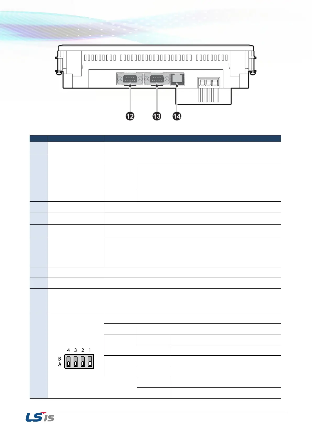
RS-232C interface
1) project data transmission
2) logging/recipe/alarm/screen data backup
3) machine software upgrade
Normal operation (default)
When upgrading Windows CE
RS-422/485 Terminal Switch On (120Ω)
RS-422/485 Terminal Switch Off (120Ω)
 Loading...