7
testing and connection of the Lidar. Please note that the interface box is not a
necessary accessory for Lidar operation.
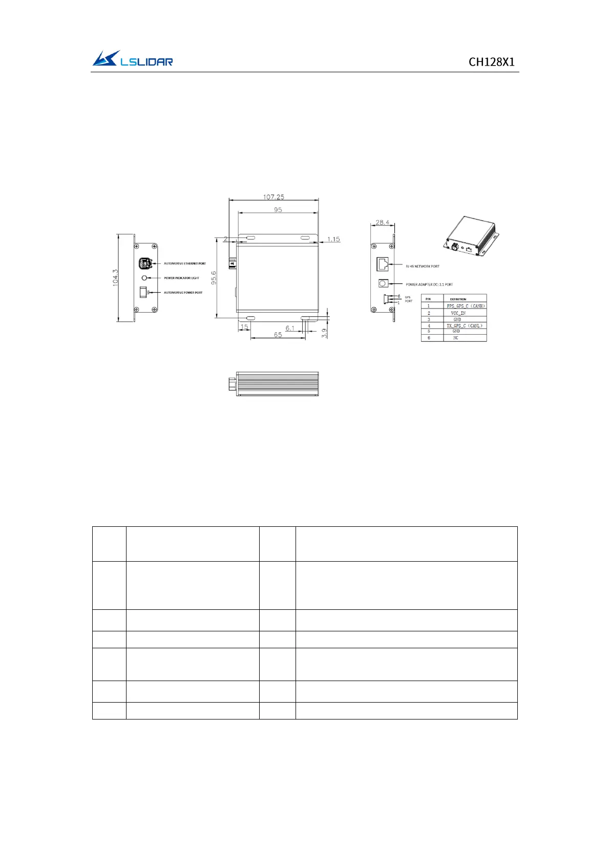
The interface box of the CH128X1 Lidar includes: an automotive ethernet port,
an automotive power port, a Φ2.1 mm DC socket, an indicator light, a RJ45
network port and a 6-PIN GPS port, as shown in Figure 2.4.
Figure 2.4 Interface Box of CH128X1
The GPS socket of the Interface Box is the SM06B-SRSS-TB presented by the JST
Company, and the recommended plug interface for the external GPS module is
JST's SHR-06V-S-B. The interface definition of the GPS is here below:
Table 2.4 The Interface Definition of the GPS
TTL level range from 3.3V to 12V; its cycle is
1 second, and the recommended pulse
width is more than 5 ms
 Loading...